
Novel fast rotating high-power electron cyclotron wave emitting antenna

A fast rotation and electron cyclotron technology, applied in electrical components, plasma and other directions, can solve the problem of inability to quickly and effectively control the deposition position of electron cyclotron waves, and achieve reliable and smooth angle control, fast pole rotation speed, and high positioning accuracy. Effect

Inactive Publication Date: 2018-05-29
SOUTHWESTERN INST OF PHYSICS
View PDF3 Cites 7 Cited by
  • Summary
  • Abstract
  • Description
  • Claims
  • Application Information

AI Technical Summary

Problems solved by technology

[0007] Aiming at the current situation that the scale of the electronic cyclotron resonance heating system of the current fusion research device is expanding day by day but the window resources of the tokamak are limited, the present invention develops a new type of fast-rotating high-power electronic cyclotron wave transmitting antenna, which takes into account the above technical requirements. At the same time, 4 beams of high-power microwaves are injected into the plasma, and the microwave injection angle can be changed in the circumferential and polar directions without mutual interference. The angle control is reliable and smooth, the positioning accuracy is high, and the polar rotation speed is fast, which solves the problem in the past. The problem that the electron cyclotron resonance heating system cannot quickly and effectively control the deposition position of the electron cyclotron wave provides a cluster-type transmitting antenna system that can emit multiple beams of microwaves

Method used


Image

  • Novel fast rotating high-power electron cyclotron wave emitting antenna
  • Novel fast rotating high-power electron cyclotron wave emitting antenna
  • Novel fast rotating high-power electron cyclotron wave emitting antenna

Examples


Embodiment Construction

[0028] A new type of fast-rotating high-power electronic cyclotron wave transmitting antenna of the present invention will be described in detail below with reference to the drawings and embodiments.

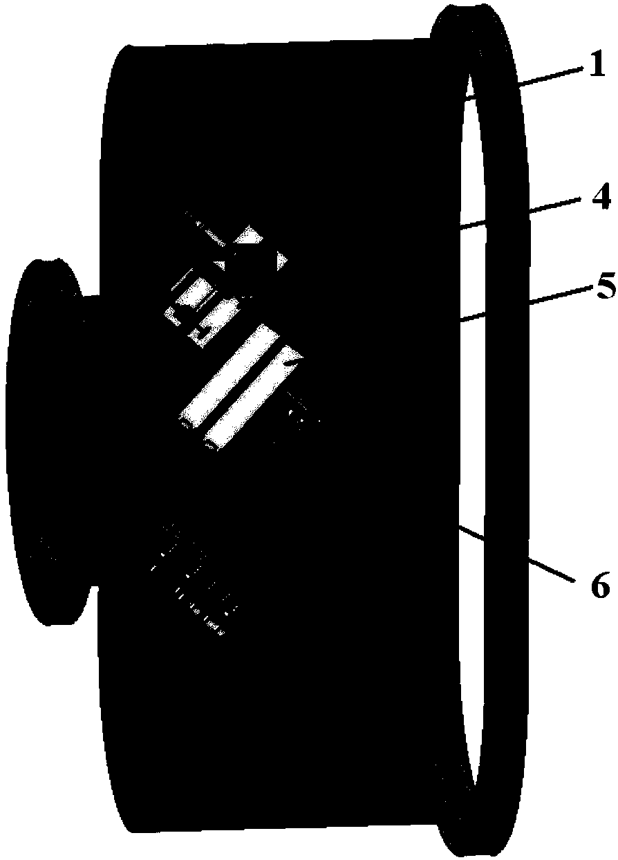
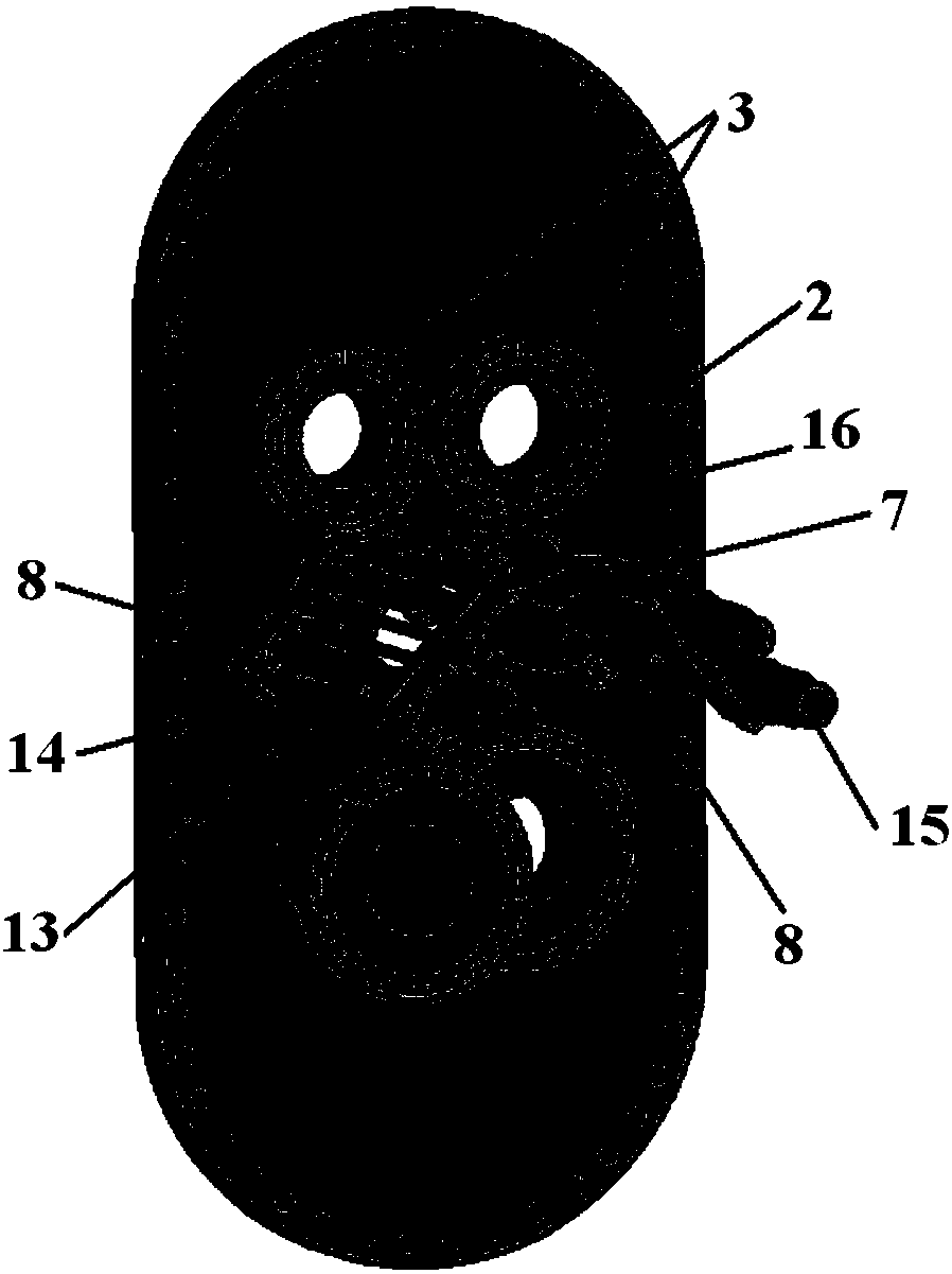
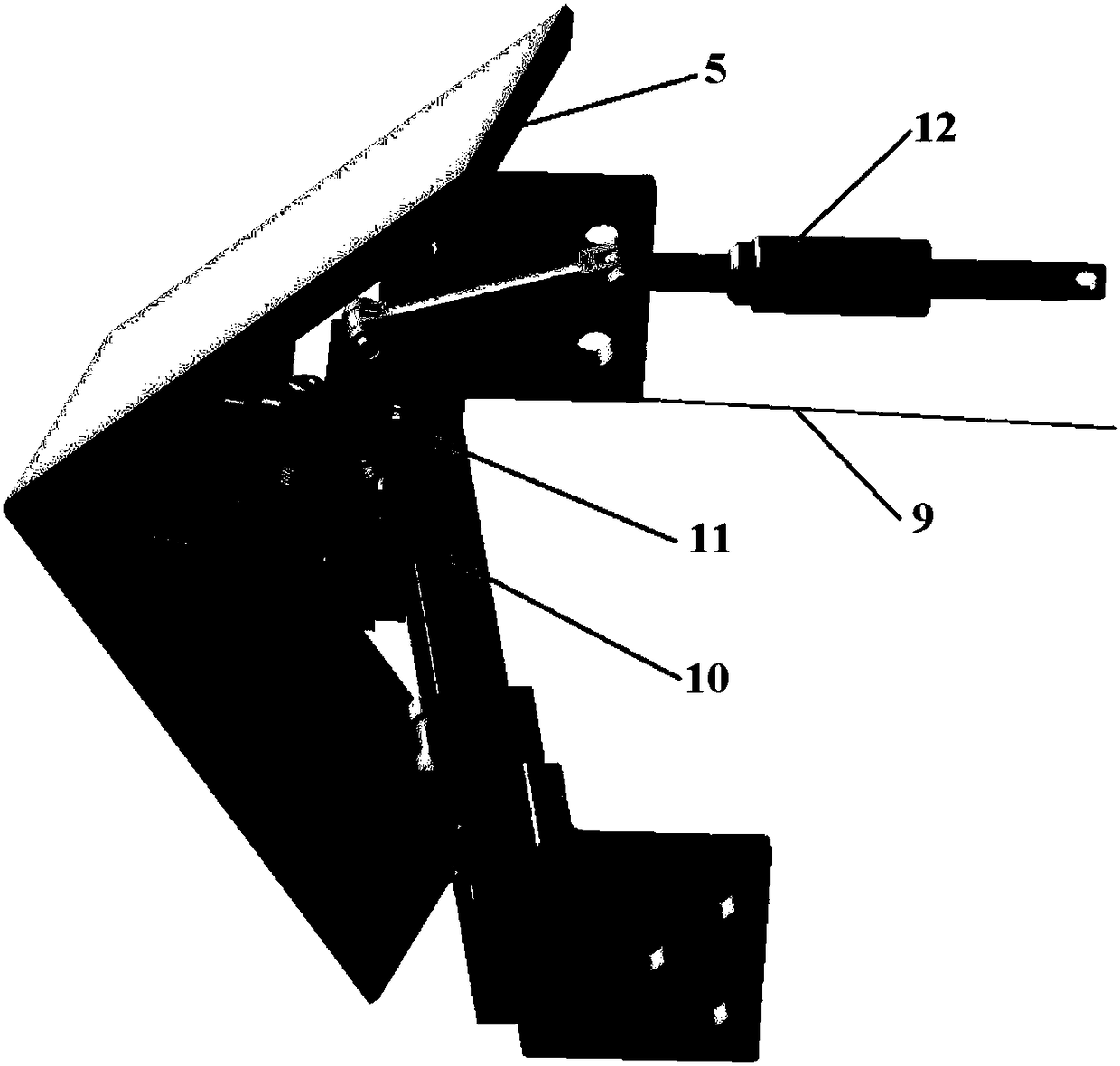
[0029] like figure 1 , 2 As shown, a novel fast-rotating high-power electronic cyclotron wave transmitting antenna of the present invention is composed of the following main components: a vacuum-sealed box 1, and one end of the vacuum-sealed box 1 is directly connected to the window of the tokamak vacuum chamber through the port flange. The flange is butted, and one end is connected with the electron gyro transmission line through the microwave sealing window fixed on the outer blind plate 2 of the antenna; the vacuum sealed box 1 is used to encapsulate the high-power microwave transmitting components in the vacuum chamber, and transmit the electron gyro system transmission line The high-power microwave is injected into the plasma; the high-power microwave emitting part include...


PUM


Abstract

The invention belongs to the field of plasma heating, and particularly relates to a novel fast rotating high power electron cyclotron wave emitting antenna. The antenna comprises a vacuum seal box, anouter blind plate connected with the vacuum seal box in a sealing manner, four vacuum seal windows on the outer blind plate, and two reflective plane mirrors and four reflective focus mirrors placedinside the vacuum seal box, wherein the four reflective focus mirrors are divided into an upper group and a lower group. A plane mirror rotating mechanism capable of making the reflective plane mirrors rotate is arranged inside the vacuum seal box. A rotation driving mechanism is arranged on the outer blind plate outside the vacuum seal box. The annular and polar injection angles of microwave canbe remotely controlled at the same time. The angle control is reliable and smooth, the positioning accuracy is high, and the polar rotation is fast. The response speed of polar angle rotation can meetthe real-time control requirement during plasma discharge. A hardware basis is provided for realizing real-time feedback control of the new classic tearing mode.

Description

technical field [0001] The invention belongs to the field of plasma heating, and in particular relates to a novel fast-rotating high-power electronic cyclotron wave transmitting antenna. Background technique [0002] The purpose of the application of high-power millimeter wave in fusion research is to increase the temperature of plasma, and the coupling efficiency between wave and plasma is one of the important indicators to measure the performance of millimeter wave system. The electronic cyclotron antenna is the medium required for the high-power millimeter wave output from the wave source (gyrotron) to reach the plasma through the transmission line. The mechanical structure and working performance of the antenna directly determine the heating and driving effect of the electronic cyclotron resonance heating system, and determine whether it can Carry out relevant physical experiments effectively. The design of the new antenna aims to ensure the stability and reliability of...

Claims


Application Information

Patent Timeline
IPC IPC(8): H05H1/18
CPCH05H1/18
Inventor 宋绍栋陈罡宇黄梅王超
Owner SOUTHWESTERN INST OF PHYSICS
Learn More