Catalyst system for ethylene selective oligomerization and ethylene oligomerization method

A catalyst and selective technology, applied in the field of catalysis, can solve the problem of low total selectivity of 1-hexene and 1-octene, and achieve the effects of low cost, simple synthesis and long catalyst life

Active Publication Date: 2018-06-01
TIANJIN UNIVERSITY OF SCIENCE AND TECHNOLOGY
View PDF18 Cites 25 Cited by
  • Summary
  • Abstract
  • Description
  • Claims
  • Application Information

AI Technical Summary

Benefits of technology

This new type of catalytic material used during this process can be very effective at making certain types of chemicals more efficiently than previous methods like cracking or dimerizing them into smaller molecules that are easier to break down by other processes such as polymers formation.

Problems solved by technology

This patented technical problem addressed in this patents relates to finding ways to efficiently manufacture alpha-olefin products such as 1 hexadecane or 1 octa-1 oleate that have better performance compared to conventional polymers like polysaccharides due to their unique molecular structures called chirality.

Method used


Image

  • Catalyst system for ethylene selective oligomerization and ethylene oligomerization method
  • Catalyst system for ethylene selective oligomerization and ethylene oligomerization method
  • Catalyst system for ethylene selective oligomerization and ethylene oligomerization method

Examples


preparation example Construction

[0080] In one embodiment of the present invention, the preparation method of catalyst system comprises the following steps:

[0081] Components a, b, and c are pre-mixed or directly added to the reaction system for in-situ synthesis. That is to say, the preparation of the catalyst is to pre-mix the ligand a, the transition metal compound b, and the activator c connected by a bridging group containing a heteroatom; Body a, transition metal compound b, and activator c are directly added to the reaction system for in-situ synthesis;

[0082] The reaction mode of the ligand a, the transition metal compound b and the activator c connected by a bridging group containing a heteroatom described in the general formula I can be reacted in a liquid phase, such as reacting under the action of a solvent. Selected solvents such as toluene, benzene and their derivatives, etc.; can also be used for solid phase reactions; and can also be used to generate catalysts through in-situ reactions du...

Embodiment 1

[0091] 1. Preparation of ligand: N, N'-bis(diisopropylphosphino)-1,1-dimethyl-N, N'-diphenylsilanediamine (C 26 h 44 N 2 P 2 Si)

[0092] (1) Preparation of Lithium Anilide

[0093] in the N 2 Add dehydrated THF (200ml) and anilinolithium (9.31g, 0.1mol) into a fully replaced stirred 500ml reactor, stir well and cool to -78°C with liquid nitrogen. Use a 100ml syringe to extract n-butyllithium hexane solution (41.6ml, 2.4mol / L), slowly add it dropwise to the above solution while stirring, keep stirring at -78°C for 1h, then rise to room temperature and continue stirring for 1 hour, then vacuum pump The solvent was removed, n-hexane (100ml) was added, stirred and dispersed, and then filtered. The obtained filtrate was vacuum-extracted at room temperature to obtain 9.97g (0.098mol, 97.8%) of the product.

[0094] (2) prepare 1,1-diisopropyl-N-phenylphosphine amine (C 12 h 20 NP)

[0095] in N 2 In an atmosphere glove box, dissolve lithium anilide (4.95g, 0.050mol) in de...

Embodiment 2

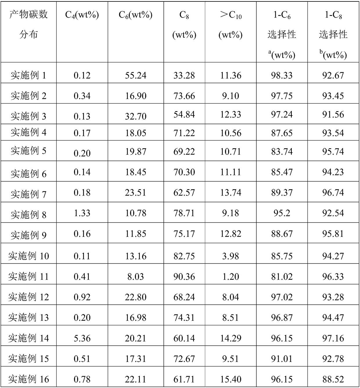
[0104] With embodiment 1. The difference is that R 1 , R 2 Both are phenyl, R 3 For cyclopentyl. Obtain 83.2g of oligomerization product, catalyst activity is 5.04×10 6 g oligomer / mol Cr·h. The distribution of the oligomerization products is shown in Table 1.


PUM


Abstract

The invention provides a catalyst system for ethylene selective oligomerization and belongs to the field of catalytic technologies. The catalyst system comprises three components which are a ligand a,a transition metal compound b, and an activator c, wherein the transition metal compound b is a metal compound of groups IVB to VIII; the activator c is a compound containing group IIIA metal; the ligand a contains at least one phosphine amine group as shown in the following general formula I, the bridging group A is the bridging group of which the main chain contains alkyl, alkenyl or aryl and aheteroatom, wherein the heteroatom is one of silicon, tin, boron, phosphorus, nitrogen, oxygen or sulfur; R<1>, R<2> and R<3> are substituent groups on two phosphine groups respectively, and R<1>, R<2> and R<3> are the same or different. The catalyst system for the ethylene selective oligomerization, disclosed by the invention, has the beneficial effects that the catalyst system is high in activity, target products of 1-hexene and 1-1octene are high in selectivity, and the content of linear alpha-olefin of C6-C8 in the products is greater than 90% in percentage by mass and a catalyst is simple in synthesis, low in cost and long in service life.

Description


Claims


Application Information

Patent Timeline
Owner TIANJIN UNIVERSITY OF SCIENCE AND TECHNOLOGY
Why Eureka
Try Eureka