
Dust removal device for thermosetting powder coating production

A technology of thermosetting powder and dust removal device, which is applied in the direction of solid separation, electrostatic separation, chemical instruments and methods, etc., which can solve the problems of difficult detection of dust removal equipment failure, poor dust adsorption effect, and difficult dust collection, etc., to achieve dust removal effect Good, simple structure, easy to collect effect

Inactive Publication Date: 2018-06-01
YANCHENG YONGYUE NEW MATERIAL CO LTD
View PDF0 Cites 2 Cited by
  • Summary
  • Abstract
  • Description
  • Claims
  • Application Information

AI Technical Summary

Problems solved by technology

It has the characteristics of no solvent, no pollution, recyclable, environmental protection, saving energy and resources, reducing labor intensity and high mechanical strength of the coating film. During the production process of powder coatings, dust will float into the air, which is not only a waste phenomenon, but also It pollutes the working environment, so a kind of dust removal equipment is needed; the existing dust removal devices have certain disadvantages in use. First, the dust adsorption effect is not good, the dust is not easy to collect, and the dust removal efficiency is low. Secondly, when the dust removal equipment fails In addition, when the dust removal device is running, the dust will be relatively concentrated, and the heat generated by mutual friction will be too high, which may cause a safety hazard of dust explosion. The friction of dust will damage the equipment and reduce the service life. Therefore, we Propose a dust removal device for thermosetting powder coating production

Method used


Image

  • Dust removal device for thermosetting powder coating production
  • Dust removal device for thermosetting powder coating production
  • Dust removal device for thermosetting powder coating production

Examples


Embodiment Construction

[0016] In order to make the technical means, creative features, goals and effects achieved by the present invention easy to understand, the present invention will be further described below in conjunction with specific embodiments.

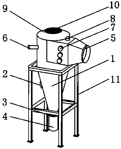
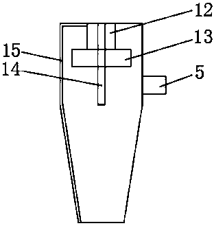
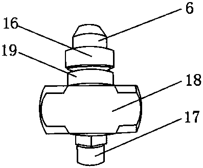
[0017] Such as Figure 1-4 As shown, including the separation cabin 1, a thermometer 2 is movably installed on the outer surface of one side of the separation cabin 1, and a connecting plate 3 is movably installed on the outer surface of the bottom end of the separation cabin 1, and an electrostatic collector is movably installed on the outer surface of the bottom end of the connecting plate 3. The dust box 4 can strengthen the adsorption of dust and facilitate the collection of dust. The dust that has been separated from the air is electrostatically adsorbed by the anode plate and will not float into the air again, improving the dust removal efficiency and better dust removal effect. The separation cabin 1 A suction chamber 5 is fixedly installed...


PUM


Abstract

The invention discloses a dust removal device for thermosetting powder coating production. The dust removal device comprises a separation cabin, a thermometer is movably installed on the outer surfaceof one side of the separation cabin, a connecting disc is movably installed on the outer surface of the bottom end of the separation cabin, an air suction chamber is fixedly installed on the outer surface of the upper end of the separation cabin, and a water pipe is movably installed at the position, above the thermometer, of one side of the separation cabin; and operation buttons are arranged onthe outer surface of the front end of the air suction chamber, and an indicating lamp is arranged on the outer surface of the upper end of the air suction chamber. According to the dust removal device for the thermosetting powder coating production, an electrostatic dust collection box, a filter screen layer and an atomizing nozzle are provided so that adsorption to dust can be enhanced, the dustcan be conveniently collected, an alarm can be given in time when the dust removal device breaks down, the internal temperature of the dust removal device can be reduced, and lubricating can be carried out on the interior of the device so that the service life of the device can be prolonged, the use is convenient, and a better application prospect is brought.

Description

technical field [0001] The invention relates to the field of dust removal devices, in particular to a dust removal device for thermosetting powder coating production. Background technique [0002] Powder coating refers to a new type of solvent-free 100% solid powder coating. It is made by mixing, crushing and sieving film-forming resins, additives, pigments and fillers. Coating construction requires electrostatic spraying and baking to form a film. It has the characteristics of no solvent, no pollution, recyclable, environmental protection, saving energy and resources, reducing labor intensity and high mechanical strength of the coating film. During the production process of powder coatings, dust will float into the air, which is not only a waste phenomenon, but also It pollutes the working environment, so a kind of dust removal equipment is needed; the existing dust removal devices have certain disadvantages in use. First, the dust adsorption effect is not good, the dust ...

Claims


Application Information

Patent Timeline
IPC IPC(8): B03C3/017B03C3/34
CPCB03C3/017B03C3/34
Inventor 杨罗王伟军
Owner YANCHENG YONGYUE NEW MATERIAL CO LTD
Learn More