Peeping mechanical arm for fusion reactor

A technology of a robotic arm and a fusion reactor, which is applied in the field of nuclear fusion engineering detection equipment, can solve problems such as low work efficiency, complex structure and difficult control, and achieve the effects of high work efficiency, wide work range and convenient operation.

Active Publication Date: 2018-06-01
YANGZHOU UNIV
View PDF7 Cites 5 Cited by
  • Summary
  • Abstract
  • Description
  • Claims
  • Application Information

AI Technical Summary

Problems solved by technology

[0005] The problems existing in the existing technology are: the endoscopic manipulator used for the fusion reactor has a high degree of freedom, the structu

Method used


Image

  • Peeping mechanical arm for fusion reactor
  • Peeping mechanical arm for fusion reactor
  • Peeping mechanical arm for fusion reactor

Examples


Embodiment Construction

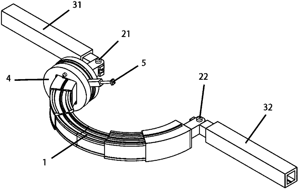
[0024] Such as figure 2 As shown, the endoscopic robotic arm for the fusion reactor of the present invention includes a semicircular horizontal guide rail 1, one end of the guide rail 1 is connected to the first base 31 through the first motor drive mechanism 21, and the other end of the guide rail 1 is connected to the first base 31 through the second motor drive mechanism 22. Connected to the second base 32 , it also includes a trolley 4 equipped with a camera 5 , the trolley 4 is placed on the guide rail 1 and can move along the horizontal guide rail 1 .

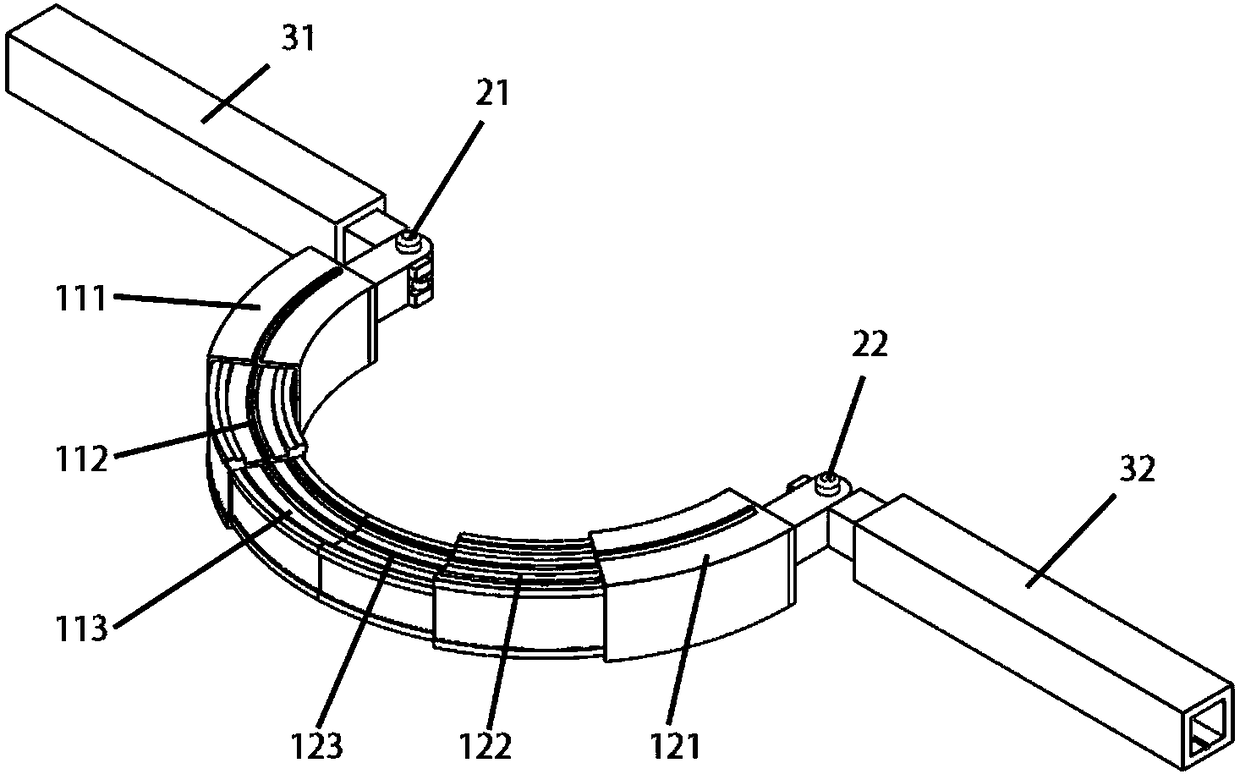
[0025] Such as image 3 as shown,

[0026] The semicircular horizontal guide rail 1 is divided into a symmetrical left guide rail 11 and a right guide rail 12;

[0027] The left guide rail 11 includes a large left track 111, a middle left track 112 and a small left track 113 which are nested in sequence. The small left track 113 can be shrunk into the middle left track 112, and the middle left track 112 can be shrunk i...


PUM


Abstract

The invention discloses a peeping mechanical arm for a fusion reactor. The peeping mechanical arm comprises a semi-circular horizontal guide rail (1); one end of the guide rail (1) is connected with afirst base (31) through a first motor driving mechanism (21), and the other end is connected with a second base (32) through a second motor driving mechanism (22); the peeping mechanical arm furthercomprises a trolley (4) provided with a camera (5); and the trolley (4) is arranged on the guide rail (1) and can move along the horizontal guide rail (1). The peeping mechanical arm for the fusion reactor is stable and reliable in work and high in efficiency.

Description

technical field [0001] The invention belongs to the technical field of nuclear fusion engineering testing equipment, in particular to an endoscopic robotic arm for fusion reactors with stable, reliable and high efficiency. Background technique [0002] Tokamak is a device for controlled nuclear fusion experiments. It uses magnetic confinement to gather high-temperature plasma in an annular cavity for experimental work in extreme environments. Since the nuclear fusion process will produce highly penetrating high-energy neutrons, high-energy neutrons will damage the device material, causing some components facing the tokamak internal annular cavity to fail to work normally, so when the fusion reactor stops working Damaged components in the reactor must be regularly maintained. [0003] The structure of the tokamak vacuum chamber is as follows: figure 1 As shown, it includes an annular cavity and several windows. The internal transverse section of the annular cavity is a circ...

Claims


Application Information

Patent Timeline
IPC IPC(8): B25J11/00B25J5/02B25J19/02
CPCB25J5/02B25J11/00B25J19/023
Inventor 张善文崔小龙金翰扬陈源源叶子安丁翔
Owner YANGZHOU UNIV
Why Eureka
Try Eureka