Magnetic adsorption units and magnetic adsorption caterpillar

A magnetic adsorption and crawler technology, applied in crawler vehicles, motor vehicles, transportation and packaging, etc., can solve the problems of poor stability, inconvenient robot movement, complex structure, etc., and achieve the effect of large load capacity

Inactive Publication Date: 2018-06-01
极创机器人智能科技(山东)有限公司
View PDF1 Cites 4 Cited by
  • Summary
  • Abstract
  • Description
  • Claims
  • Application Information

AI Technical Summary

Problems solved by technology

For example, a magnetic adsorption type wall-climbing robot disclosed in the Chinese invention patent application with the patent application number 201110436290.0 has a magnetic adsorption unit on its chain crawler, wherein the magnetic adsorption unit includes: yoke iron 25, magne

Method used


Image

  • Magnetic adsorption units and magnetic adsorption caterpillar
  • Magnetic adsorption units and magnetic adsorption caterpillar
  • Magnetic adsorption units and magnetic adsorption caterpillar

Examples


Embodiment 1

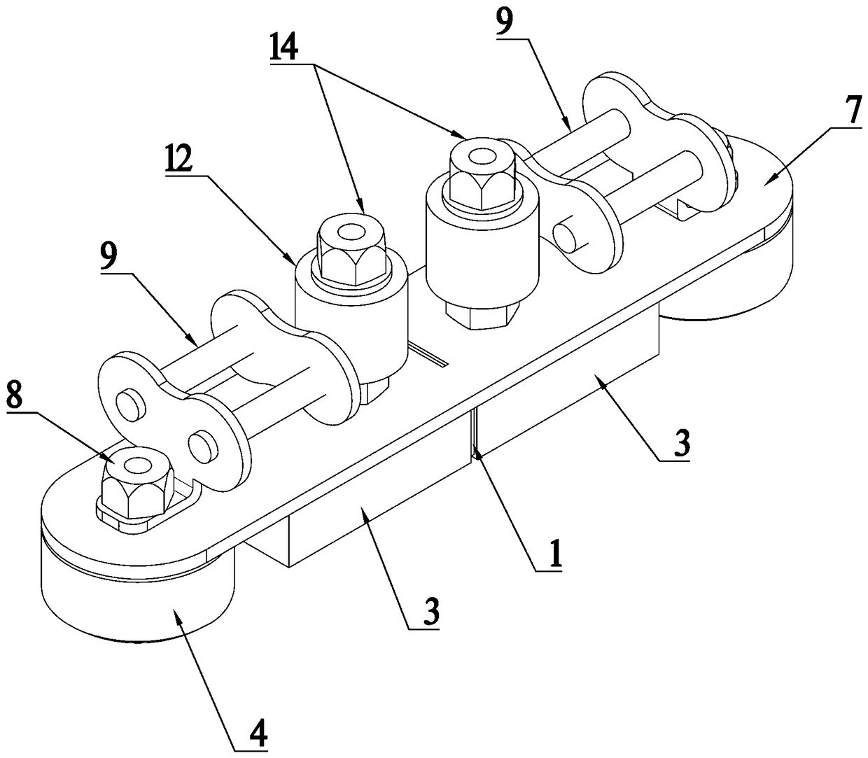
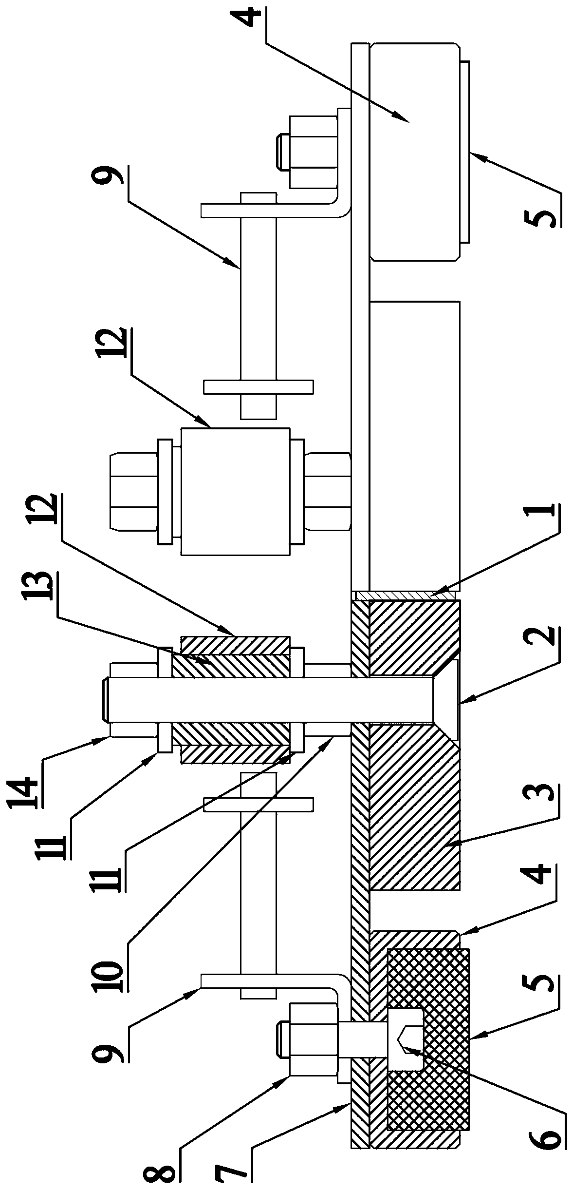
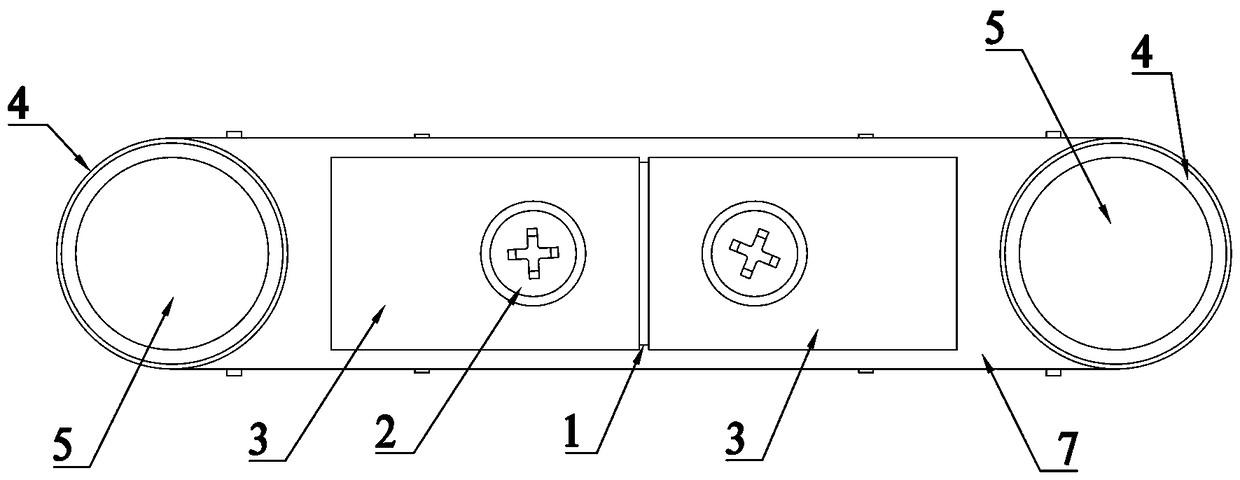
[0033] Such as Figure 1-4 The shown magnetic adsorption unit includes a base plate 7, which is in the shape of a slat, and its two ends are semicircular structures. One side of the base plate 7 is fixedly provided with a magnet 3, and the other side is provided with a guide anti-off mechanism. The guide anti-off mechanism includes two columns symmetrically arranged on the base plate 7, and a guide sleeve is arranged on the upright column. The gap between the first column and the guide sleeve is used for embedding the guide plate. Described magnet 3 adopts powerful magnet.

[0034] Two magnets 3 are arranged side by side on the said substrate 7, and a magnet spacer 1 is arranged between the two magnets 3, and the adsorption force of the two magnets 3 can be enhanced by the magnet spacer 1, and the said substrate 7 is provided with a fixing groove 15 , the magnet separator 1 is fixedly arranged in the fixing groove 15 .

[0035] The two magnets 3 are fixed on the base plate ...

Embodiment 2

[0040] Such as Figure 5 with Image 6 A magnetic adsorption crawler is shown, which includes several magnetic adsorption units as described in Embodiment 1. Bending plate chain links 9 are respectively fixedly arranged on both sides of the guide anti-off mechanism, and between several magnetic adsorption units The magnetic adsorption track is formed by connecting the bent plate chain links 9 with each other.

[0041] In other words, the magnetic adsorption track includes two curved plate chains arranged side by side, and the curved plate chains are connected end to end to form a closed loop. The two ends of the magnetic adsorption unit described in the first embodiment are fixed on the chains of the curved plate chains. The section rotates accordingly.

[0042] The middle part of the inner side of the magnetic adsorption crawler is equipped with a continuous guide anti-off mechanism, which is used to cooperate with the anti-off guide plate of the driving mechanism of the wa...


PUM


Abstract

The invention relates to magnetic adsorption units and a magnetic adsorption caterpillar. The magnetic adsorption units comprise substrates, magnets and antiskid pads are fixed to one sides of the substrates, driving chains and guide anti-fall caterpillar mechanisms are arranged at the other sides of the substrates, each guide anti-fall caterpillar mechanism comprises two columns symmetrically arranged on the substrate, and the columns are provided with rotatable guide covers. The magnetic adsorption caterpillar comprises several magnetic adsorption units, bending plate chain joints are fixedto the two sides of each guide anti-fall mechanism respectively, and the magnetic adsorption units are mutually connected through the bending plate chain joints to constitute the magnetic adsorption caterpillar. Every two columns form each clamping mechanism, each clamping mechanism is used for clamping each guide plate, through the arrangement of guide covers, friction between the guide covers and the guide plates is reduced, running is smooth, and on one hand, it can be guaranteed that the caterpillar runs steadily and stably; on the other hand, the caterpillar can be prevented from being separated out from conveying wheels. A magnetic adsorption caterpillar wall climbing robot can have a high load bearing capability, the load bearing capability is 150 kg or above, and the wall climbingrobot is driven to be applied in the industrial level.

Description

technical field [0001] The invention relates to the field of magnetic adsorption wall-climbing robots, in particular to a magnetic adsorption unit and a magnetic adsorption track. Background technique [0002] The magnetic adsorption wall climbing robot is a special robot, which is mostly used for specific operations such as detection, maintenance, welding, or grinding on the magnetic wall surface under harsh, dangerous, and extreme working conditions. At present, magnetic adsorption robots have been widely used in the production and construction of steel structures such as nuclear industry, petrochemical industry, construction industry, fire department, and shipbuilding industry. [0003] In engineering applications, magnetic adsorption wall-climbing robots need to solve a series of problems such as adsorption, driving, steering, obstacle surmounting, adaptation to small curvature surfaces, loads of working parts, and even automatic control. At present, people are constantl...

Claims


Application Information

Patent Timeline
IPC IPC(8): B62D55/265
CPCB62D55/265
Inventor 周振龙
Owner 极创机器人智能科技(山东)有限公司
Why Eureka
Try Eureka