
Ground source well backfilling system and ground source well backfilling method

A ground-source well and ground-source technology, applied in excavation, construction, infrastructure engineering, etc., can solve problems such as poor backfill effect, easy blockage of returned materials, and unclean air discharge, so as to achieve easy blockage, good heat exchange effect, The effect of high backfill density

Inactive Publication Date: 2018-06-01
DALIAN ZHONGYING ENERGY MANAGEMENT
View PDF5 Cites 0 Cited by
  • Summary
  • Abstract
  • Description
  • Claims
  • Application Information

AI Technical Summary

Problems solved by technology

[0003] In order to solve the problems in the prior art that the return material is easily blocked in the middle of the well, the air is not discharged cleanly, the backfill effect is poor, the heat exchange effect is not good, and the speed of the grouting pipe cannot be controlled, etc., the present invention provides a ground source well backfill System and backfilling method, the grouting material is filled from the bottom of the deep well by back pressure grouting, through the overflowing slurry, the original air and water in the well are gradually discharged upwards, the backfilling ground source well is not easy to block, the air is completely discharged, and the backfilling density is high. Higher, better heat transfer effect

Method used


Image

  • Ground source well backfilling system and ground source well backfilling method
  • Ground source well backfilling system and ground source well backfilling method

Examples


Embodiment 1

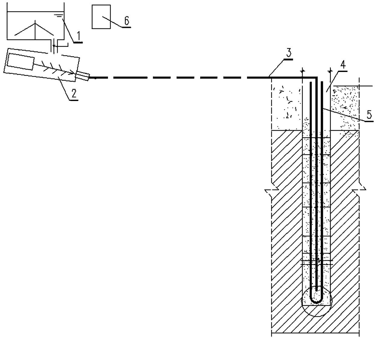
[0043] A ground source well backfilling system, comprising: a mixer 1, a grouting pump 2, a grouting pipe 3, a double U heat exchanger 5 and a pipe lifter, the mixer 1 is connected to the grouting pump 2, and the injection The grout pump 2 is connected to one end of the grouting pipe 3, the other end of the grouting pipe 3 is connected to the double U heat exchanger 5, and the pipe lifter is connected to the grouting pipe 3 for lifting the Describe the grouting pipe 3.

[0044] Further, it also includes a filler metering bucket 6 for metering the backfill material put into the mixer 1 .

[0045] Further, a controller is also included, the controller is connected with the grouting pump 2 and the pipe lifter, and is used for controlling the grouting pump 2 and the pipe lifter.

[0046] Further, the controller is a PLC control system.

[0047] Further, the grouting pump 2 is a screw type grouting pump.

[0048] The present invention also includes a ground source well backfilli...

Embodiment 2

[0076] A ground source well backfilling method, which adopts the bottom grouting backfilling construction method. The grouting pipe 3 is inserted into the bottom of the deep well together with the double U heat exchanger 5. Slurry, gradually discharge the original air and water in the well upwards; lift the pipe while grouting, until the grouting material flows out from the wellhead of the ground source, which proves that the backfill of the entire deep well has been completed and the backfill has been compacted.

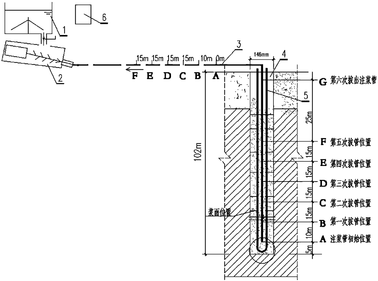
[0077] The speed of lifting the grouting pipe is determined according to the volume of the backfill. The volume of the backfill is calculated from the volume of the deep well and the volume occupied by the heat exchanger, and then the backfill is calculated according to the volume of backfill into the well during the grouting process. The height of the grouting pipe can be determined according to the height of the backfill.

Embodiment 3

[0079] as attached figure 2 As shown, the grouting pipe 3 is inserted into the bottom of the ground source well 4 together with the double U heat exchanger 5, and the mouth of the grouting pipe is 5 meters away from the bottom of the well.

[0080] According to the volume of the deep well and the volume occupied by the heat exchanger, the volume of the backfill is calculated, and the backfill is measured by the filler metering barrel 6 and put into the mixer 1 in six times. After the grouting pump 2 is pumped into the ground source well 4, backfill is added to the mixer 1 from the filler metering barrel 6 again.

[0081] Strictly control the pulling speed of the grouting pipe during the grouting process. If it is too fast, the air in the well will not be exhausted. If it is too slow, the filler will easily squeeze the buried pipe. Do not pull the pipe until a complete tank of dry material is grouted to ensure that the grouting pipe is buried below the grout surface.

[0082...


PUM


Abstract

The invention relates to a ground source well backfilling system and a ground source well backfilling method and belongs to the field of backfilling construction of a ground source well. The ground source backfilling system comprises a mixer, a grouting pump, a grouting pipe, a double-U-shaped heat exchanger and a pipe lifter; the mixer is connected with the grouting pump; the grouting pump is connected with one end of the grouting pipe; the other end of the grouting pipe is connected with the double-U-shaped heat exchanger; and the pipe lifter is connected with the grouting pipe and is used for lifting the grouting pipe. The ground source backfilling system and the ground source backfilling method provided by the invention have the beneficial effects that a grout material is reversely compressed upwards from the bottom of a deep well so as to realize grouting filling; by the upwards-overflowing grout, the original air and moisture in the well can be gradually discharged upwards, blocking is barely generated in backfilling of the ground source well, the air is discharged completely, the backfilling compactness is high, and a better heat exchange effect is achieved.

Description

technical field [0001] The invention belongs to the field of ground source well backfill construction, in particular to a ground source well backfill system and a backfill method. Background technique [0002] Ground source heat pump technology has been widely used in China due to its energy-saving properties, especially the vertical buried tube ground source heat pump technology, which needs to drill a large number of deep wells for heat exchange, bury heat exchange tubes, and then use heat exchangers with good thermal conductivity. The packing is densely filled, but at present, some of them use natural backfilling, and some of them put the grouting pipe at the wellhead for grouting backfilling. These two methods are easy to block in the middle of the well, the air is not exhausted, and the backfilling effect is poor, resulting in heat transfer Not good, there are still a small number of bottom grouting backfilling methods, although it can solve the compactness problem, but...

Claims


Application Information

Patent Timeline
IPC IPC(8): E02D17/06E02D17/12
CPCE02D17/06E02D17/12
Inventor 杜以臣马志勇谢飞
Owner DALIAN ZHONGYING ENERGY MANAGEMENT
Learn More