Real-time monitoring gas supply device for GIS equipment storage and gas supply method

A real-time monitoring and equipment technology, applied in the direction of container discharge method, measuring device, container structure installation device, etc., can solve the problems of not installing pressure gauges and inability to ensure, so as to prevent internal corrosion, prolong life, and reduce production The effect of maintenance costs

Pending Publication Date: 2018-06-01
HUIZHOU POWER SUPPLY BUREAU OF GUANGDONG POWER GRID CO LTD
View PDF10 Cites 0 Cited by
  • Summary
  • Abstract
  • Description
  • Claims
  • Application Information

AI Technical Summary

Problems solved by technology

The equipment is often not equipped with a pressure gauge with a corresponding micro-positive pressure range, or even directly without a pressure gauge, which cannot ensure that the GIS equipment meets the "micro-positive pressure" state required by the above provisions

Method used


Image

  • Real-time monitoring gas supply device for GIS equipment storage and gas supply method
  • Real-time monitoring gas supply device for GIS equipment storage and gas supply method

Examples


Embodiment 1

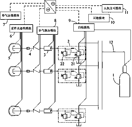
[0033] figure 1 It is the first embodiment of a real-time monitoring gas replenishing device for GIS equipment storage in the present invention, including several groups of decompression devices 2, precision pressure gauges 3, check valves 4 and air barriers connected in sequence through air guide tubes 12. Device 5, decompression device 2 is also connected with common nitrogen device 1;

[0034] It also includes a self-inspection module 9, an air supply execution module 8, a sampling and inspection module 6, and an air supply decision-making module 7. The self-inspection module 9 is connected to the nitrogen device 1 and the decompression device 2, and the air supply execution The module 8 is connected with the check valve 4 and the precision pressure gauge 3, the sampling and inspection module 6 is connected with the air separation device 5, the sampling and inspection module 6 is connected with the gas replenishment decision module 7, and the gas replenishment decision modu...

Embodiment 2

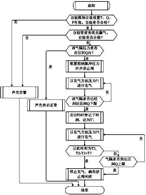
[0043] figure 2Embodiment 2 of a real-time monitoring gas supply method for GIS equipment storage of the present invention comprises the following steps:

[0044] S1: T, Q, and P are valid for the self-test module setting. Whether the self-inspection is qualified; if the self-inspection is not qualified, the sound and light alarm will directly enter the end process; if the self-inspection is qualified, perform the next step S2;

[0045] S2: After step S1, self-check whether there is air leakage in the pipeline system; if the self-inspection detects air leakage in the pipeline, an audible and visual alarm will be issued, and the end process will be directly entered; if there is no air leakage in the pipeline during the self-inspection, go to the next step S3;

[0046] S3: After step S2, judge whether the air separation pressure is in the interval Q; if the air separation pressure is in the interval Q, the sound and light indicate normal, and directly enter the end process; if...


PUM


Abstract

The invention relates to the field of substation equipment, in particular to a real-time monitoring gas supply device for GIS equipment storage. The device comprises multiple sets of pressure reducingdevices, precise pressure gauges, check valves and gas separation devices connected through gas guide pipes in sequence; and the pressure reducing devices are connected with a common nitrogen device.The device further comprises a self-inspection module, a gas supply actuation module, a sampling and polling module and a gas supply decision module; the self-inspection module is connected with thenitrogen device and the pressure reducing devices; the gas supply actuation module is connected with the check valves and the precise pressure gauges; the sampling and polling module is connected withthe gas separation devices, and is connected with the gas supply decision module; and the gas supply decision module is connected with the gas supply actuation module. The device is simple in structure, can monitor the pressure in the gas separation devices in the storage process of GIS equipment in real time, and performs the gas supply operation to prevent external moisture from entering the GIS equipment in the storage process to cause the rusting problem in the GIS equipment.

Description

technical field [0001] The invention relates to the field of substation equipment, and more specifically, to a real-time monitoring gas supply device and a gas supply method for GIS equipment storage. Background technique [0002] The construction of substations is carried out according to the forecast of power load demand, according to the planning and design, usually in several stages, so the substation will inevitably face the situation of equipment expansion. Gas-insulated combined electrical appliances, referred to as GIS equipment, are typical equipment used in substations. [0003] The delivery date of substation equipment is often stipulated in the contract, based on the expected commissioning date, and the selected equipment is based on the date. The electrical equipment assembly needs to be carried out after the corresponding civil works meet the preliminary acceptance of the electrical equipment foundation. In reality, the equipment is often delayed according to ...

Claims


Application Information

Patent Timeline
Patent Type & Authority Applications(China)
IPC IPC(8): F17C5/06F17C13/02F17C13/04G01L19/12
CPCF17C5/06F17C13/025F17C13/04G01L19/12F17C2205/0335F17C2205/0323F17C2225/0123F17C2223/0123F17C2221/014F17C2250/043F17C2227/04
Inventor 黄泽荣王铁柱高士森袁晓杰叶欢欢蔡素雄包卫军郭琳施理成
Owner HUIZHOU POWER SUPPLY BUREAU OF GUANGDONG POWER GRID CO LTD
Why Eureka
Try Eureka