High-power microwave source strong electromagnetic environment air pressure measuring device

A barometric pressure measurement device, high-power microwave technology, applied in the direction of measuring devices, measuring fluid pressure, instruments, etc., can solve problems such as permanent damage, barometer cannot read, limit the scope of application, etc.

Pending Publication Date: 2019-03-08
INST OF APPLIED ELECTRONICS CHINA ACAD OF ENG PHYSICS
View PDF0 Cites 0 Cited by
  • Summary
  • Abstract
  • Description
  • Claims
  • Application Information

AI Technical Summary

Problems solved by technology

Due to the frequent switching operations of high-power power electronic devices in the HPM source system, steep transient pulses will be generated; high-power microwaves are radiated by antennas, and their side lobes, back lobes, and reflected microwaves can be radiated by near-field coupling and far-field Form high-frequency conduction and radiation interference, causing electromagnetic environment pollution to electrical grid equipment and nearby electronic units such as measurement and control systems, resulting in functional failure or permanent damage
When the electronic pressure gauge is directly installed on the HPM source, there are often failures such as the barometer cannot be read, the screen is black, and even the machine cannot be turned on, which limits its application range. Therefore, it is the HPM measurement and control system to expand the applicability of the air pressure measurement device in the strong electromagnetic environment. One of the focuses of the research
[0003] The digital communication pressure gauge usually used in the pressure measurement device of the HPM source system has a built-in pressure sensor, which adopts a metal casing, and the cable outlet is used to transmit the pressure signal remotely, and the DC 24V power supply. Therefore, there are three main factors that affect the pressure measurement: 1. Coupling input through the power supply line electromagnetic interference

Method used


Image

  • High-power microwave source strong electromagnetic environment air pressure measuring device
  • High-power microwave source strong electromagnetic environment air pressure measuring device
  • High-power microwave source strong electromagnetic environment air pressure measuring device

Examples


Embodiment Construction

[0024] The technical solution of the present invention will be further described in detail below in conjunction with the accompanying drawings, but the protection scope of the present invention is not limited to the following description.

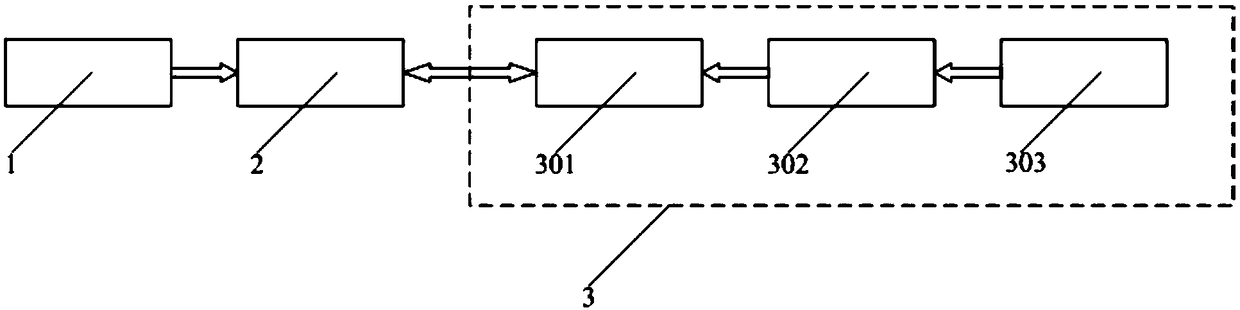
[0025] Such as figure 1 As shown, a high-power microwave source strong electromagnetic environment air pressure measurement device includes an insulating transition section 1, a digital communication pressure gauge 2 and a signal conversion processing unit 3; wherein the signal conversion processing unit 3 includes an electrical / optical conversion module 301 (electrical / Optical conversion module 301 is used to convert and process the air pressure measurement signal for external transmission), power conversion module 302 and filter 303;

[0026] The digital communication pressure gauge 2 is installed on the pressure vessel through the insulating transition section 1, which has good sealing performance;

[0027] The air pressure signal col...


PUM


Abstract

The invention discloses a high-power microwave source strong electromagnetic environment air pressure measuring device. The device comprises a digital communication pressure gauge, an insulating transition section and a signal conversion processing unit. The signal conversion processing unit comprises an electricity / light conversion module, a power conversion module and a filter. The digital communication pressure gauge is mounted on a pressure container through the insulating transition section, and power input is provided through the power conversion module; an external power source is connected to the signal conversion processing unit and connected to the power conversion module through the filter. The digital communication pressure gauge acquires air pressure signals, the air pressuresignals are output in a serial bus mode, the digital communication pressure meter is connected with the electricity / light conversion module, and multi-mode optical fiber remote transmission is adopted. By means of the air pressure measuring device, the purpose of remotely monitoring the air pressure of the pressure container in real time is achieved, and the requirement that the device is appliedto high-power microwave source strong electromagnetic interference environments is further met.

Description

technical field [0001] The invention relates to a high-power microwave source strong electromagnetic environment pressure measuring device. Background technique [0002] The air pressure measurement device completes the air pressure monitoring of the high power microwave (HPM) source pressure vessel, providing real-time information for the normal operation of the system. As an important measuring instrument, the barometer is divided into two types: mechanical and electronic. The former has strong environmental adaptability, but has no electrical signal output, so it cannot realize long-distance monitoring and can only be observed on site; the latter usually has standard serial communication The electrical output interface of the protocol can be used for on-site observation and long-distance transmission. Due to the frequent switching operations of high-power power electronic devices in the HPM source system, steep transient pulses will be generated; high-power microwaves ar...

Claims


Application Information

Patent Timeline
Patent Type & Authority Applications(China)
IPC IPC(8): G01L11/00G01L19/08
CPCG01L11/00G01L19/086
Inventor 金晖康强孙良宝罗敏谭杰罗光耀向飞王淦平李春霞刘忠
Owner INST OF APPLIED ELECTRONICS CHINA ACAD OF ENG PHYSICS
Why Eureka
Try Eureka