Temperature control device of power communication cabinet

A temperature control device and power communication technology, applied in the direction of non-electric variable control, temperature control, control/regulation system, etc., can solve the problems of burning cabinets, poor heat dissipation, short circuit, etc., to enrich the human-computer interaction environment and improve heat dissipation Good effect and scalability

Inactive Publication Date: 2018-06-01
张韩
View PDF0 Cites 1 Cited by
  • Summary
  • Abstract
  • Description
  • Claims
  • Application Information

AI Technical Summary

Problems solved by technology

[0003] With the development of communication technology and the increase in the integration of communication equipment, the heat generated by the operation of communication equipment has greatly increased, and the communication cabinets in the substation are all with front glass doors and rear metal doors, and the heat dissipation effect is poor. In summer, it is often necessary to open the cabinet door to dissipate heat.
Long-term operation of the equipment in a high-temperature environment will cause accelerated aging of the equipment and increase the failure rate
If opening the cabinet door does not meet the operation requirements of the substation, and opening the cabinet door will greatly increase the dust of the equipment, which will affect the safe and stable operation of the equipment
At present, the temperature of the power communication system computer room is required to be controlled between 22±2°C, and the overall computer room has an air conditioner to control the temperature. However, due to the difference in the number of equipment in the cabinet and the heat dissipation, the temperature difference between the individual cabinets is large, and there are many installations. The heat generated by the cabinet is higher than the standard temperature for a long time, which will cause high temperature damage to the equipment, and in severe cases, it will cause accidents such as short circuit or burning of the cabinet

Method used


Image

  • Temperature control device of power communication cabinet
  • Temperature control device of power communication cabinet

Examples


Embodiment Construction

[0016] In order to make the object, technical solution and advantages of the present invention clearer, the present invention will be further described in detail below in conjunction with the accompanying drawings and embodiments. It should be understood that the specific embodiments described here are only used to explain the present invention, not to limit the present invention.

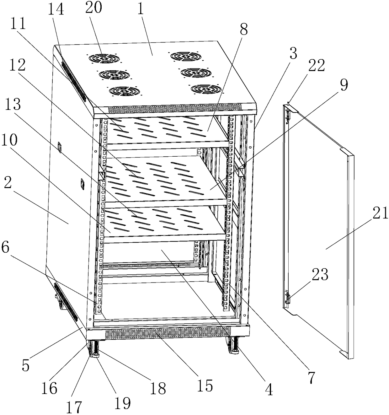
[0017] see figure 1 , the temperature control device for a power communication cabinet includes a communication cabinet body, and the communication cabinet body includes a top cover body 1, a left side board body 2, a right side board body 3, a rear side board body 4, and a bottom board body 5 The first row of installation columns 6 is installed on the left side plate body 2 of the communication cabinet body, the second row of installation columns 7 is installed on the right side panel body 3, and the first row of installation columns 6 The first partition plate 8, the second partition plate 9 and...


PUM


Abstract

The invention discloses a temperature control device of a power communication cabinet. The device comprises a communication cabinet body. The communication cabinet body comprises a top cover body, a left side plate body, a right side plate body, a back side plate body and a base plate body. The left side plate body of the communication cabinet body is provided with a first row of mounting verticalcolumns, and the right side plate body is provided with a second row of mounting vertical columns. A first separator plate, a second separator plate and a third separator plate are mounted between the first row of mounting vertical columns and the second row of mounting vertical columns. A heat radiating trough A is mounted at the periphery of the top cover body. A heat radiating trough B is mounted at the periphery of the base plate body. A plurality of heat radiating windows are machined on the top cover body. One side of the right side plate body is provided with a door plate. The communication cabinet body is internally provided with a temperature control system. The temperature control system comprises a single-chip microcomputer controller, a temperature acquisition module, a signalamplifying conditioning circuit, an analog-to-digital converting module, a display module, an alarm module, an RS485 communication module, a remote upper computer, a functional button input module, arelay A, a relay B, a heater and a cooler.

Description

technical field [0001] The invention relates to the technical field of communication cabinets, in particular to a temperature control device for a power communication cabinet. Background technique [0002] The power communication cabinet is a kind of outdoor cabinet, which refers to the cabinet made of metal or non-metal materials that is directly under the influence of natural climate and does not allow unauthorized operators to enter and operate. It provides wireless communication stations or wired network station workstations. Equipment for outdoor physical work environments and safety systems. Power communication cabinets are suitable for installation in outdoor environments, such as roadsides, parks, roofs, mountainous areas, and flat ground. Base station equipment, power supply equipment, batteries, temperature control equipment, transmission equipment and other supporting equipment can be installed in the cabinet or the above equipment The installation space and heat...

Claims


Application Information

Patent Timeline
Patent Type & Authority Applications(China)
IPC IPC(8): G05D23/20
CPCG05D23/20
Inventor 张韩
Owner 张韩
Why Eureka
Try Eureka