Ring main unit with heat sink

A technology of heat dissipation device and ring network cabinet, applied in the field of ring network cabinet, can solve the problems of not really achieving high heat dissipation, single structure of heat dissipation device, burning of internal circuits, etc., so as to improve work efficiency and service life, reduce temperature, and improve use. effect of life

Inactive Publication Date: 2018-06-01
NINGHAI COUNTY POWER EQUIP BUILD OR REPAIR FACTORY
View PDF1 Cites 5 Cited by
  • Summary
  • Abstract
  • Description
  • Claims
  • Application Information

AI Technical Summary

Problems solved by technology

[0002] The ring network cabinet is a set of high-voltage switchgear installed in a steel plate metal cabinet or made into an assembled interval ring network power supply unit. It is widely used in load centers such as urban residential quarters, high-rise buildings, large public buildings, and factories. In the power distribution substation and box-type substation, as far as the current technical conditions are concerned, because the ring main unit is often in a power-on state, the working environment itself is poor, and because it is an electrical equipment, its requirements for temperature are relatively high. If it is too high, it will cause the internal circuit to burn out and cause a short circuit. For example, the application number is 201710653723.5, which is called a ring network cabinet with heat dissipation and anti-condensation functions, including cabinet body, top cover, heat dissipation device, anti-condensation device, temperature Sensor and controller, its heat dissipation purpose is to utilize heat dissipation device to carry out heat dissipation, and this heat dissipation device comprises heat sink, blower one and heat dissipation cavity, and described heat dissipation chamber comprises blower two, heat dissipation chamber and ventilation duct, and its heat dissipation mode is, through blower one The cabinet body is radiated, and the fan 2 is arranged in the heat dissipation chamber, and the ventilation pipes are respectively arranged at the corners of the bottom plate and the side wall of the heat dissipation chamber, so that the ventilation pipes can realize the ventilation of the air inside the heat dissipation chamber and the outside air. Convection to achieve the heat exchange of heat inside the heat dissipation chamber, but the structure of the above heat dissipation device is single, and it cannot really achieve high heat dissipation effect during heat dissipation, and the heat dissipation fins of the above heat dissipation device are arranged on the two symmetrical outer walls of the cabinet body. Although such a setting method is convenient for manual replacement of heat sinks, the heat sinks exposed on the outer wall of the cabinet are prone to dust entry, which leads to inability to achieve heat dissipation, and finally leads to low working efficiency and short service life of the cabinet. And the cabinet body and top cover cannot be opened, so it is inconvenient to manually clean up dust and maintain

Method used


Image

  • Ring main unit with heat sink
  • Ring main unit with heat sink

Examples


Embodiment 1

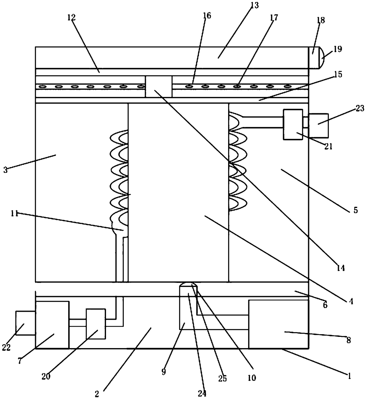
[0021] Refer to as figure 1As shown, a ring main unit with a cooling device includes a body 1 and a cooling device 2, the cooling device 2 is installed in the body 1, and a high-voltage component box 3 and a cable box 4 are also arranged in the body 1 And the operating mechanism box 5, the cable box 4 is located between the high-voltage component box 3 and the operating mechanism box 5, the operating mechanism box 5, the high-voltage component box 3 and the cable box 4 are all located above the cooling device 2, the cooling device 2 includes a mounting frame 6, a water storage tank 7, an air pump 8, an air duct 9 and an air spray head 10, one end of the air spray head 10 runs through the installation frame 6, and the other end of the air spray head 10 is connected to the air pump 8 through the air duct 9 , the air pump 8 is located on the right side of the water storage tank 7, the water storage tank 7 is provided with a heat dissipation pipe 11, one end of the heat dissipatio...

Embodiment 2

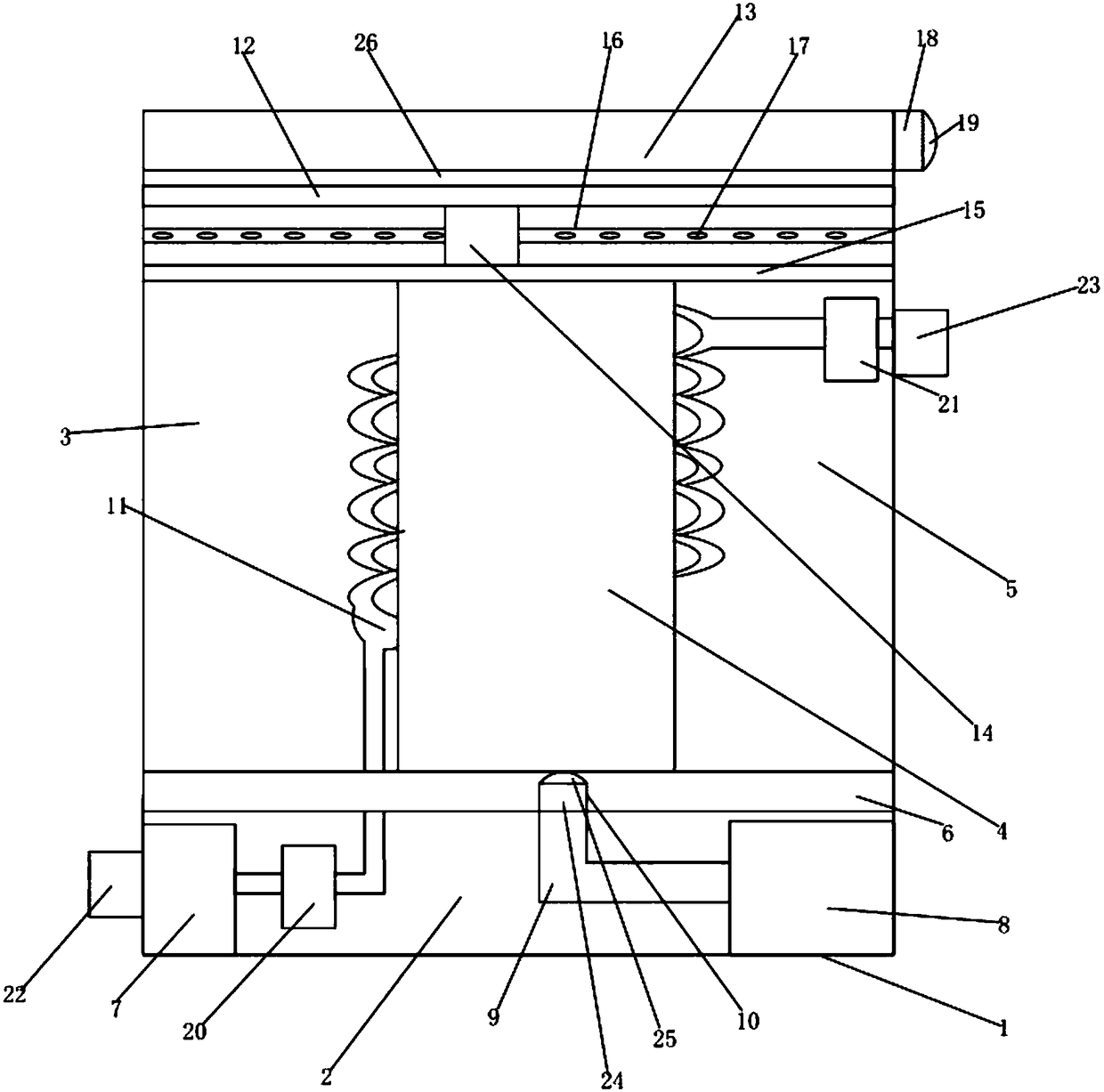
[0024] Refer to as figure 2 As shown, this embodiment is substantially the same as Embodiment 1, the difference is that a slide rail 26 is provided between the dust-proof plate 13 and the ventilation duct 12, and one end of the slide rail 26 slides with the dust-proof plate 13 The other end of the slide rail 26 is fixedly connected with the ventilation duct 12, so that the dustproof plate can be pushed to open manually, so that the dustproof plate slides along the slide rail to separate from the ventilation duct, which solves the problem that the top of the cabinet body in the prior art cannot To solve the problem and realize the purpose of smooth operation and low noise of the dust plate and the ventilation duct.


PUM


Abstract

The invention discloses a ring main unit with a heat sink. The rain main unit comprises a body and a heat sink, wherein a high voltage part box, a cable box and an operating mechanism box are also arranged in the body, the heat sink comprises an installation frame, a water storage tank, an air pump, an air guide pipe and a jet head, the water storage tank is provided with a heat radiating pipe, one end of the jet head penetrates through the installation frame, the other end of the jet head is connected with the air pump by virtue of the air guide pipe, the water storage tank is provided with the heat radiating pipe, so that cooling water in the water storage box enters the heat radiating pipe, the heat radiating pipe performs the heat exchange for the heat from the outer side surface of acable in the body as well as the heat radiated by the high voltage part box and the operating mechanism box, the air pump sends the cold air from the air guide pipe to the jet head then being ejectedby the jet head, the ejected cold air circulates the heat accumulated on the lower portions of the high voltage part box, the cable box and the operating mechanism box, and the body achieves purposesof good heat radiating effect and long service life.

Description

technical field [0001] The invention discloses the technical field of ring network cabinets, and more specifically discloses a ring network cabinet with a cooling device. Background technique [0002] The ring network cabinet is a set of high-voltage switchgear installed in a steel plate metal cabinet or made into an assembled interval ring network power supply unit. It is widely used in load centers such as urban residential quarters, high-rise buildings, large public buildings, and factories. In the power distribution substation and box-type substation, as far as the current technical conditions are concerned, because the ring main unit is often in a power-on state, the working environment itself is poor, and because it is an electrical equipment, its requirements for temperature are relatively high. If it is too high, it will cause the internal circuit to burn out and cause a short circuit. For example, the application number is 201710653723.5, which is called a ring netw...

Claims


Application Information

Patent Timeline
Patent Type & Authority Applications(China)
IPC IPC(8): H02B1/56H02B1/30
CPCH02B1/565H02B1/30
Inventor 吴伟峰沈国鸿舒建华鲍建军孔丹蕴应晓烽陈君睿
Owner NINGHAI COUNTY POWER EQUIP BUILD OR REPAIR FACTORY
Why Eureka
Try Eureka