

Redundant energy acquiring circuit for power module and control method thereof
A power module and circuit technology, applied in the field of power module redundant energy acquisition circuit and control, can solve the problems of sub-module capacitor overvoltage damage, bypass switch capacitor short circuit, inability to provide bypass switch closing command, etc., to avoid The effect of forced outage and improved reliability
- Summary
- Abstract
- Description
- Claims
- Application Information
AI Technical Summary
Problems solved by technology
Method used
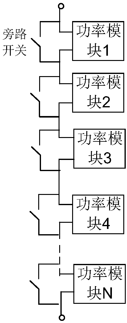
Image

Examples
Embodiment 1
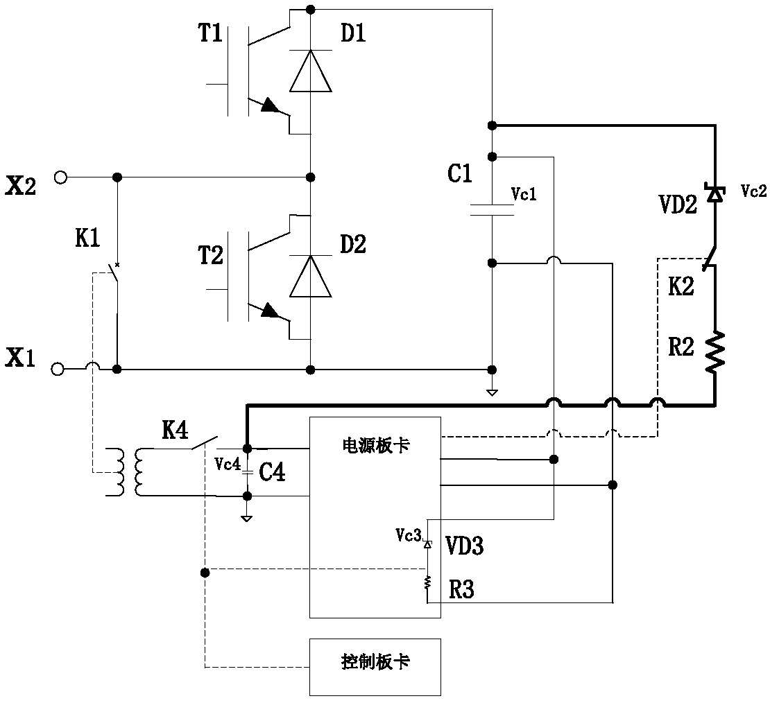
[0054] refer to figure 1 , the power module redundant energy-taking circuit proposed by the present invention:
[0055] A power module redundant energy acquisition circuit, the power module includes at least one power semiconductor device, a first capacitor C1, and a first bypass switch K1; the energy acquisition circuit includes a first voltage regulator tube VD1, a second voltage regulator Tube VD2, second switch K2, first resistor R1, second resistor R2, second capacitor C2, power board and control board; the anode of the first regulator tube VD1 is connected to the positive pole of the first capacitor C1, The cathode is connected to the positive pole of the second capacitor C2 after being connected in series with the first resistor R1, and the negative pole of the second capacitor C2 is connected to the negative pole of the capacitor C1; the anode of the second voltage regulator tube VD2 is connected to the positive pole of the first capacitor C1, and the negative pole It...
Embodiment 2
[0061] refer to Figure 4 , a power module redundant energy-taking circuit of an isolated power supply proposed by the present invention,
[0062] Wherein, in this implementation, the power supply board in the energy-taking circuit of the power module is an isolated power supply board, and the isolated power supply board includes an isolation transformer. The energy harvesting circuit also includes a fourth switch K4, which is connected in series between the negative pole of the second capacitor C2 and the negative pole of the first capacitor C1, and is in a closed state when the power board is not working, and is in a closed state when the power board is working normally. is in a disconnected state.
[0063] Described switch K3, switch K4 and switch K2 can be mechanical switch or relay, also can be electronic switch, as thyristor, IGBT, IGCT, GTO or MOSFET; The trigger signal of described switch K3, switch K4 and switch K2 comes from power supply board or control board.
...
PUM
 Abstract
Description
Claims
Application Information