A sleeve-type shock-reducing flow equalizer

A sleeve-type, flow-disc technology, applied in chemical/physical processes, chemical instruments and methods, etc., can solve the problem of affecting the hydrogenation reactor distributor effect, the uneven depth of the liquid layer on the distribution plate, and the ability to resist the inclination of the tray Weakness and other problems, to achieve the effect of saving reactor space, optimizing material distribution, and stabilizing the liquid layer

Active Publication Date: 2021-12-07
CHINA PETROLEUM & CHEM CORP +1
View PDF5 Cites 0 Cited by
  • Summary
  • Abstract
  • Description
  • Claims
  • Application Information

AI Technical Summary

Problems solved by technology

The bubble cap distributor based on the suction principle is easily covered or partially covered, resulting in uneven material distribution, and when the inlet liquid is unevenly distributed, it will seriously affect the effect of the top distributor of the hydrogenation reactor
[0021] In view of the technical problems that the traditional gas-liquid distributor has weak anti-tray tilting ability and the influence of the uneven depth of the liquid layer on the distribution plate, it is necessary to develop a gas-liquid distributor with the function of reducing the impact and equalizing the flow, with small volume, good distribution effect and low installation accuracy. The new internal component technology is used to reduce the strong impact force formed by the residual kinetic energy of the fluid entering the reactor, and is used to eliminate the "wave pushing" phenomenon of the liquid in the inclined flow state on the liquid layer on the distribution plate, so as to realize the uniform distribution of the fluid

Method used


Image

  • A sleeve-type shock-reducing flow equalizer
  • A sleeve-type shock-reducing flow equalizer
  • A sleeve-type shock-reducing flow equalizer

Examples


Embodiment 1

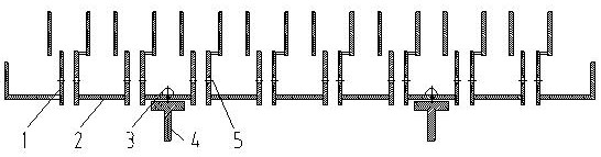
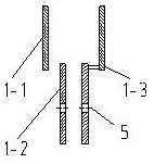
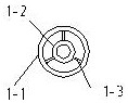
[0064] After the transformation, the sleeve-type shock-reducing equalizing plate of the present invention is added in the upper head, using such as figure 1 The sleeve-type shock-reducing equalizer shown is used in combination with a common ERI-type bubble-cap gas-liquid distributor. The main parameters of the sleeve-type flow equalizer: the height of the impact reduction cylinder is preferably 300mm; the diameter of the impact reduction cylinder is preferably 150mm; the upper edge of the impact reduction cylinder is provided with triangular slots, and the height of the tooth grooves is 10% of the height of the impact reduction cylinder. The horizontal gap between the impact reduction cylinder and the chimney distributor is preferably 30mm; the cross-sectional area of ​​the impact reduction cylinder is 5 times the cross-sectional area of ​​the chimney distributor; the bottom edge of the impact reduction cylinder overlaps with the chimney distributor; the overlapping position is...


PUM


Abstract

The invention discloses a sleeve type shock reducing and equalizing plate. The sleeve-type flush-reducing equalizer includes a tray and several chimney-type distributors arranged on the tray; the chimney-type distributor includes a downcomer and a shock-reducing barrel arranged at the upper end of the downcomer; Both the flushing barrel and the downcomer are cylindrical structures with openings at both ends, the flushing reducing barrel and the downcomer are arranged up and down, and the diameter of the flushing reducing barrel is larger than that of the downcomer. The shock reducing and equalizing plate of the present invention is a newly added internal member of the reactor, which is arranged in the idle space of the upper head of the hydrogenation reactor, or the upper end of the cylinder body of the hydrogenation reactor. The shock reducing and equalizing plate of the present invention can reduce the strong impact force formed by the residual kinetic energy when the fluid enters the reactor, and eliminate the "wave pushing" phenomenon of the inclined streamline formed when the central point enters the liquid layer of the distribution plate. The sleeve-type shock-reducing flow equalizer of the present invention is suitable for all hydrogenation reactors, and is especially suitable for hydrogenation reactors with large liquid-gas ratio and large scale.

Description

technical field [0001] The invention relates to a sleeve type shock reducing and equalizing plate, which belongs to the field of chemical equipment. The sleeve-type shock-reducing flow equalizer of the present invention is a new internal component for the reactor. The sleeve-type impact reducing and equalizing plate of the present invention is suitable for various hydrogenation reactors, especially suitable for large-scale hydrogenation reactors with relatively large liquid and gas. Background technique [0002] In recent years, with the rapid development of my country's national economy and the enhancement of environmental protection awareness, the quality and environmental protection requirements of petrochemical products are getting higher and higher. In order to meet the needs of processing sour crude oil, meet the ever-increasing demand for chemical raw materials, and improve product quality, the importance and role of hydrogenation technology in the oil refining indus...

Claims


Application Information

Patent Timeline
Patent Type & Authority Patents(China)
IPC IPC(8): B01J8/02B01J8/00
CPCB01J8/008B01J8/0278B01J2208/00911B01J2208/0092
Inventor 彭德强王璐瑶孟凡飞陈新刘杰
Owner CHINA PETROLEUM & CHEM CORP
Why Eureka
Try Eureka