Device for testing input speed of aeroengine centrifugal sensor

A technology of aero-engine and input speed, which is applied in measurement devices, linear/angular velocity measurement, devices using electric/magnetic methods, etc. Improve the accuracy of detection and data, simple structure, real and reliable data

Active Publication Date: 2018-06-05
AECC AVIATION POWER CO LTD
View PDF8 Cites 1 Cited by
  • Summary
  • Abstract
  • Description
  • Claims
  • Application Information

AI Technical Summary

Problems solved by technology

[0004] This type of engine only has the speed of the engine, and the input speed of the centrifugal sensor is calculated through the transmission ratio, so the actual speed cannot be known
Centrifugal sensor installation form such as figure 1 As shown, the entire structure is compact and cannot directly measure the input speed of the centrifugal sensor

Method used


Image

  • Device for testing input speed of aeroengine centrifugal sensor
  • Device for testing input speed of aeroengine centrifugal sensor
  • Device for testing input speed of aeroengine centrifugal sensor

Examples


Embodiment Construction

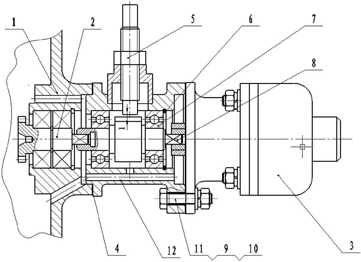
[0032] The present invention is described in further detail below in conjunction with accompanying drawing:

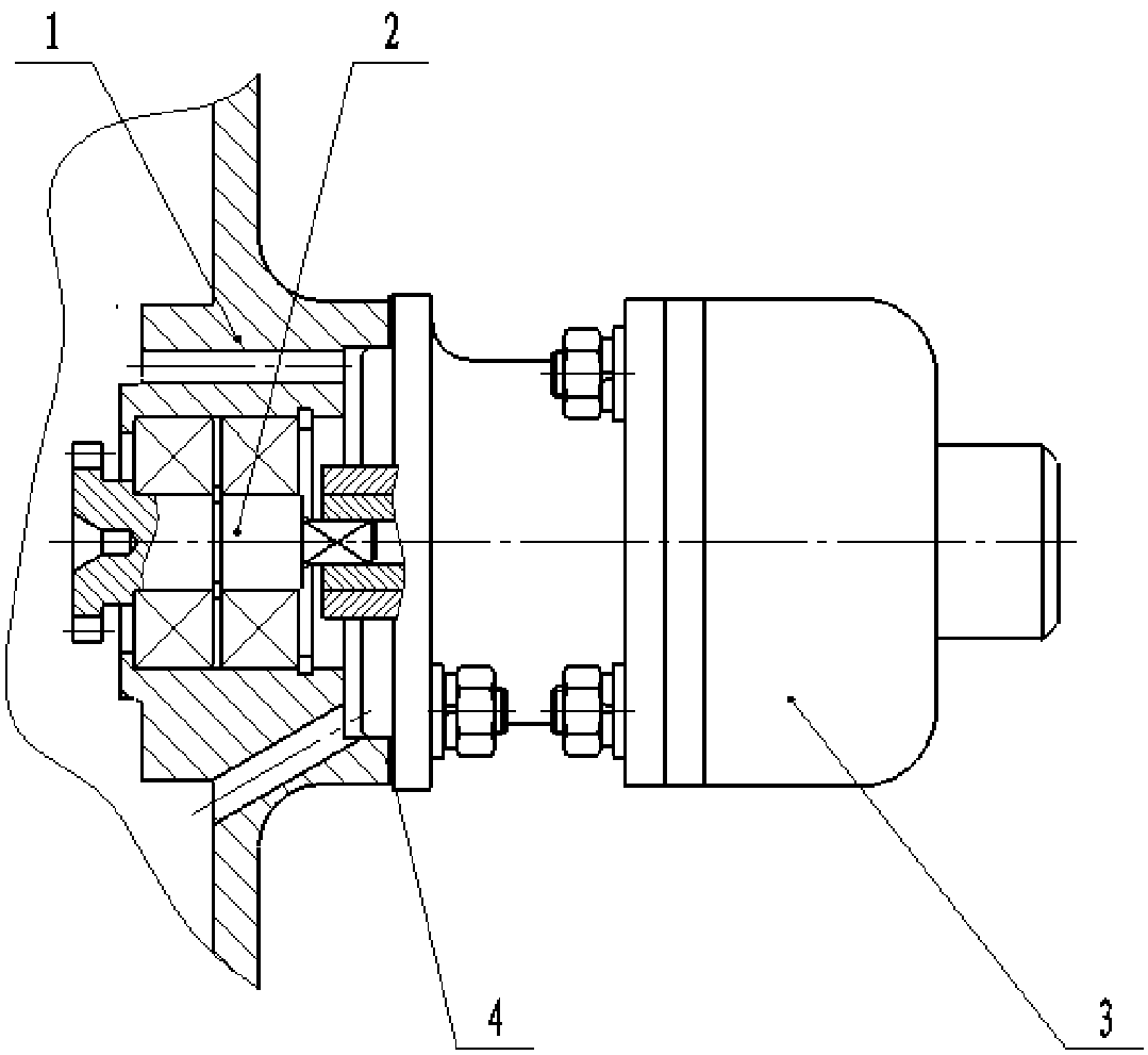
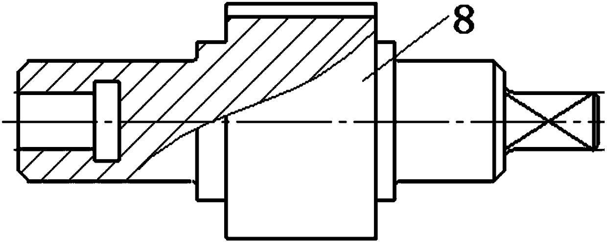
[0033] like figure 2 As shown, an aeroengine centrifugal sensor input rotational speed test device includes an adapter seat 12 connected between the engine case 1 and the centrifugal sensor 3, one end of the adapter seat 12 is press-fitted into the engine case 1, A sealing gasket 4 is provided between the adapter seat 12 and the attached casing 1, and the other end of the adapter seat 12 is connected with the centrifugal sensor 3 through bolts 9 and nuts 11, and a washer 10 is arranged on the bolts 9 and nuts 11. The seat 12 is a middle-pass structure, the adapter seat 12 is provided with a counting gear shaft 8, the middle of the counting gear shaft 8 is a counting tooth, one end of the counting gear shaft 8 is connected to the input shaft of the centrifugal sensor 3, and the other end of the counting gear shaft 8 is connected to the hair attached The driven gear sh...


PUM


Abstract

The invention discloses a device for testing the input speed of an aeroengine centrifugal sensor. The device is provided with a change-over seat between an engine accessory casing and the centrifugalsensor, the change-over seat is provided with a through hole, then two ends of a counting gear shaft installed in the change-over seat are respectively connected with an input shaft of the centrifugalsensor and a driven gear shaft in the engine accessory casing, the middle of the counting gear shaft is provided with counting teeth, the side wall of the change-over seat is provided with an eddy current sensor mounting hole, a probing head of the eddy current sensor directly faces towards the counting teeth on the counting gear shaft so as to perform signal acquisition on the speed of the counting gear shaft, and the counting gear shaft is connected with the driven gear shaft and capable of coaxially rotating, so that data acquisition for the speed of the counting gear shaft is the speed ofthe driven gear shaft and the actual input speed of the centrifugal sensor. The device is simple in structure, authentic and reliable in data, does not need to modify the structure of the engine accessory casing and the centrifugal sensor, and greatly improves the detection and data accuracy of the input speed of the aeroengine centrifugal sensor.

Description

technical field [0001] The invention belongs to aero-engine testing technology, in particular to an aero-engine centrifugal sensor input rotational speed testing device. Background technique [0002] During the operation of the aero-engine, due to the needs of panting prevention and performance, the engine air release belt will be closed and opened according to the speed of the engine. The closing and opening of the deflation belt is automatically controlled by the input speed sensed by the centrifugal sensor installed on the engine casing. When the engine speed reaches the preset speed of the centrifugal sensor, the deflation belt is closed and the deflation belt signal light is at the same time. On; when the speed is lower than the preset speed, the deflation belt is opened, and the signal light of the deflation belt is off at the same time. [0003] In recent years, some problems such as abnormal closing failure of the deflation belt and flickering of the deflation belt ...

Claims


Application Information

Patent Timeline
Patent Type & Authority Applications(China)
IPC IPC(8): G01P3/49G01P3/44
CPCG01P3/443G01P3/49
Inventor 马英田慧清刘忠华范毅王秀丽张成贵于杰陈喆
Owner AECC AVIATION POWER CO LTD
Why Eureka
Try Eureka