Antenna of terminal

An antenna and terminal technology, applied in the field of terminal antennas, can solve the problems of poor antenna performance and poor adjustment effect, and achieve the effect of improving antenna performance, improving performance, and improving frequency adjustment effect.

Active Publication Date: 2018-06-05
BEIJING XIAOMI MOBILE SOFTWARE CO LTD
View PDF9 Cites 11 Cited by
  • Summary
  • Abstract
  • Description
  • Claims
  • Application Information

AI Technical Summary

Problems solved by technology

[0006] In order to solve the problem of poor adjustment effect and poor antenna performance when adjusting the antenna frequency, an embodiment of the present disclosure provides a terminal antenna

Method used


Image

  • Antenna of terminal
  • Antenna of terminal
  • Antenna of terminal

Examples


Embodiment Construction

[0062] In order to make the purpose, technical solutions and advantages of the present disclosure clearer, the present disclosure will be further described in detail below in conjunction with the accompanying drawings. Obviously, the described embodiments are only some of the embodiments of the present disclosure, not all of them. . Based on the embodiments in the present disclosure, all other embodiments obtained by persons of ordinary skill in the art without creative efforts fall within the protection scope of the present disclosure.

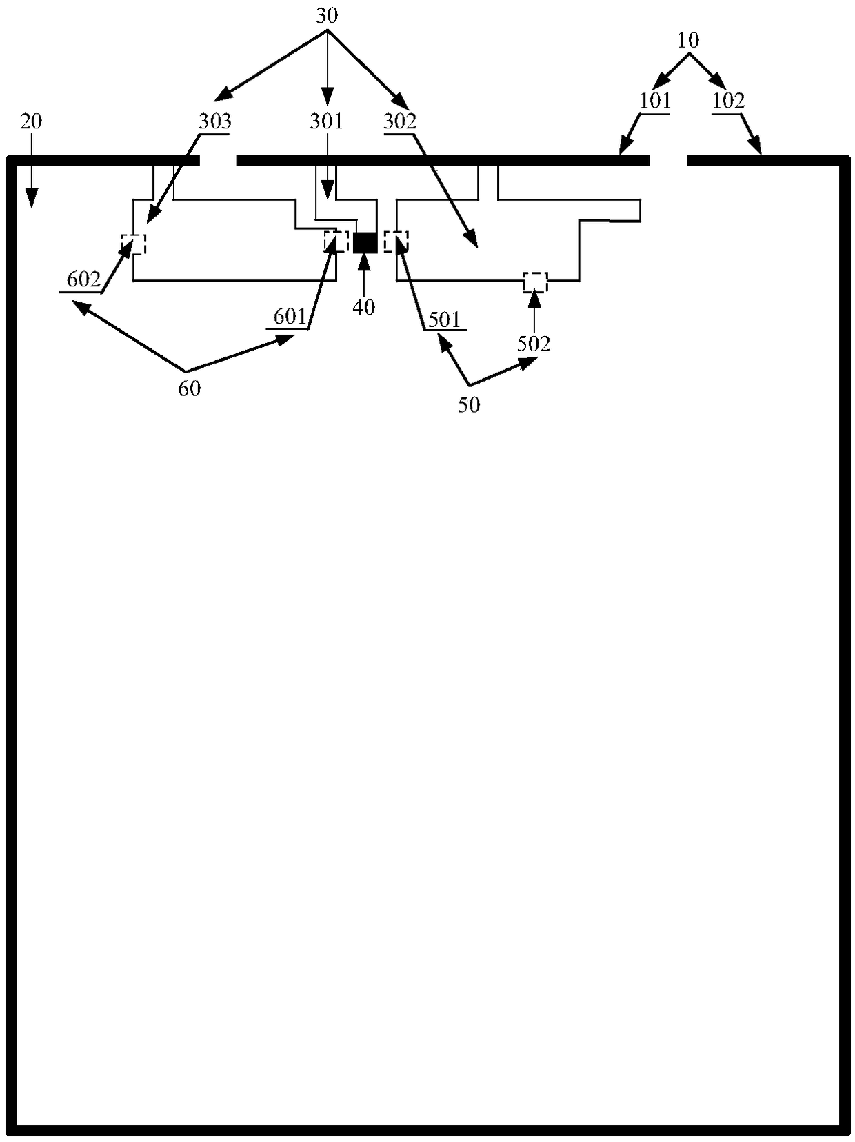
[0063] figure 1 is a schematic structural diagram of an antenna of a terminal shown according to an exemplary embodiment, as shown in figure 1 As shown, the antenna includes:

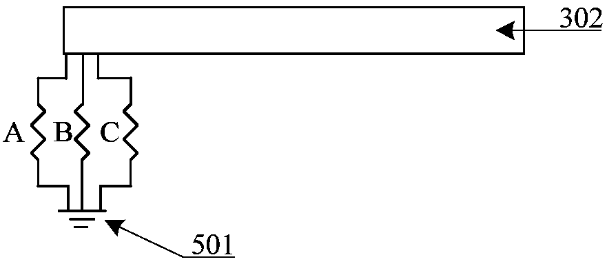
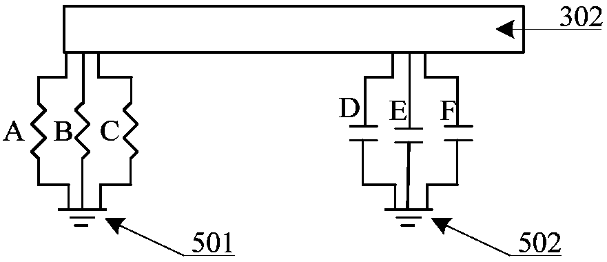
[0064] The metal frame 10 of the terminal, the circuit board 20 located in the metal frame 10, at least three radiation units 30 and at least two variable elements arranged on the circuit board 20, the at least three radiation units 30 include a first radiation unit ...


PUM


Abstract

The present invention relates to an antenna of a terminal and belongs to the antenna technological application field. The antenna includes a bottom frame, a side frame, a circuit board, at least two variable elements, a first radiating unit, a second radiating unit, and a third radiating unit; the circuit board is provided with a signal feeding point, at least two first grounding points and at least two second grounding points; the signal feeding point is connected with the bottom frame through the first radiating unit; the at least two first grounding points are connected with the bottom frame through the second radiating unit with first slot coupling realized, and low-frequency resonance is generated; the at least two second grounding points are connected with the side frame through thethird radiating unit with second slot coupling realized, and intermediate-frequency resonance is generated; variable elements are connected in series between at least one first grounding point and thesecond radiating unit; and variable elements are connected in series between at least one second grounding point and the third radiating unit. With the antenna of the present invention adopted, the problem of a poor effect in antenna frequency adjustment can be solved, the effect of the frequency adjustment of the antenna can be improved, and the performance of the antenna can be improved. The antenna of the present invention is used to send and receive signals.

Description

technical field [0001] The present disclosure relates to the application field of antenna technology, and in particular to an antenna for a terminal. Background technique [0002] The antenna is a device used to send and receive signals in the terminal. When designing the antenna in the terminal, it is necessary to avoid the electronic components inside the terminal to avoid interference with the signal of the antenna. The antenna in the terminal generally adopts a plane inverted F (English: Planar Inverted F-shaped Antenna; abbreviation: PIFA) antenna, inverted F (English: Inverted F-shaped Antenna; abbreviation: IFA) antenna or loop (English: Loop) antenna, etc. [0003] In practical applications, changes in the terminal's use environment often affect the signal of the terminal's antenna. In related technologies, the frequency of the antenna is adjusted by adjusting the properties of the variable electronic components connected in series between the ground point and the ra...

Claims


Application Information

Patent Timeline
Patent Type & Authority Applications(China)
IPC IPC(8): H01Q1/24H01Q1/50H01Q5/20H01Q5/307H01Q5/314
CPCH01Q1/242H01Q1/50H01Q5/20H01Q5/307H01Q5/314
Inventor 薛宗林
Owner BEIJING XIAOMI MOBILE SOFTWARE CO LTD
Why Eureka
Try Eureka