Powder storage warehouse provided with auxiliary discharging device

A discharge device and powder technology, applied in the direction of loading/unloading, transportation and packaging, conveying bulk materials, etc., can solve problems such as the decline in discharge efficiency, and achieve improved discharge efficiency, good applicability, and high discharge efficiency Effect

Inactive Publication Date: 2018-06-08
赵世青
View PDF3 Cites 1 Cited by
  • Summary
  • Abstract
  • Description
  • Claims
  • Application Information

AI Technical Summary

Problems solved by technology

However, it has been found in practice that this type of pneumatic reclaiming device for powder silos mainly relies on the self-weight of the powder to achieve reclaiming. For powder materials with high physical viscosity and poor fluidity, as well as powders that are easy to absorb moisture and have hydration activity material, its discharge efficiency has decreased

Method used


Image

  • Powder storage warehouse provided with auxiliary discharging device
  • Powder storage warehouse provided with auxiliary discharging device
  • Powder storage warehouse provided with auxiliary discharging device

Examples


Embodiment 1

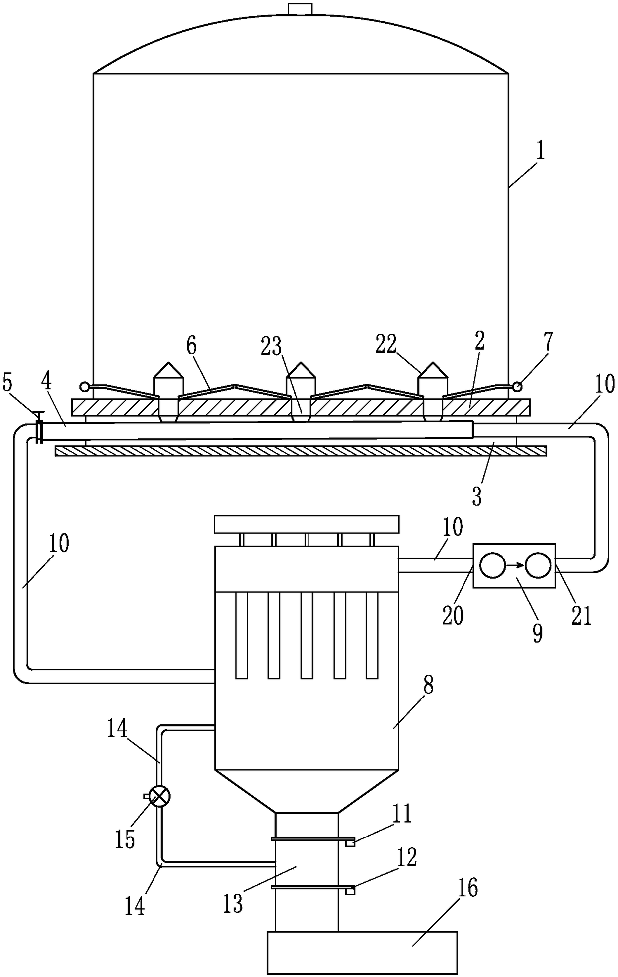
[0014] Such as figure 1 The shown powder storehouse of the present invention is provided with auxiliary discharge device, comprises storehouse body 1 and storehouse bottom 2, and the upper surface of storehouse bottom 2 is provided with fluidization bar 6, and fluidization bar 6 is connected with air supply pipeline 7, storehouse A retrieving device is set in the corridor 3 in the bottom 2, and the retrieving device includes a material conveying pipe 4, which extends to the outside of the warehouse, and the discharge end of the material conveying pipe 4 outside the warehouse is provided with a material flow control The valve 5 also includes an auxiliary discharge device. The auxiliary discharge device includes a dust collector 8 and a positive and negative pressure integrated fan 9. The negative pressure end 20 of the negative pressure integrated fan 9 is connected, and the positive pressure end 21 of the positive and negative pressure integrated fan 9 is connected with the ai...

Embodiment 2

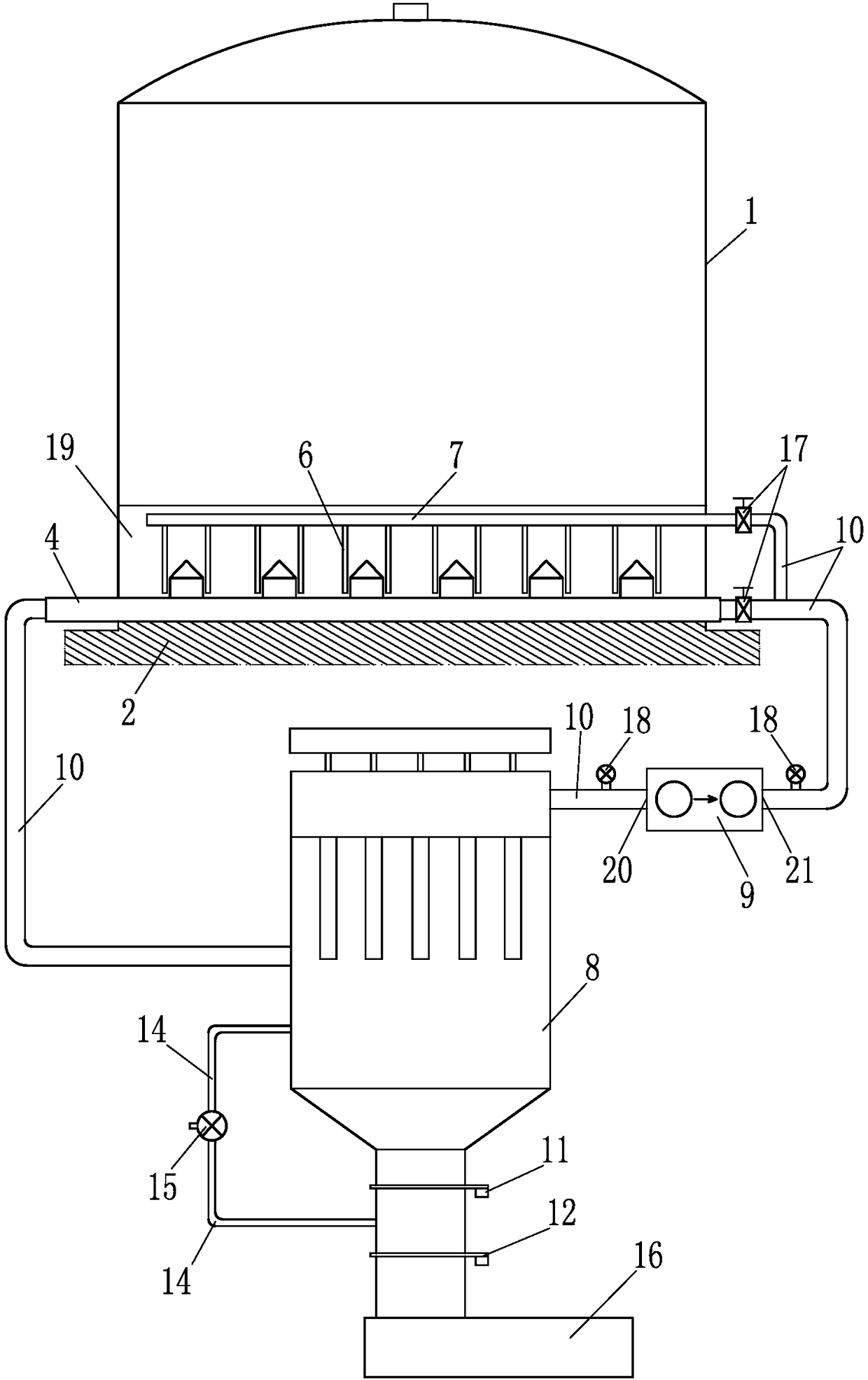
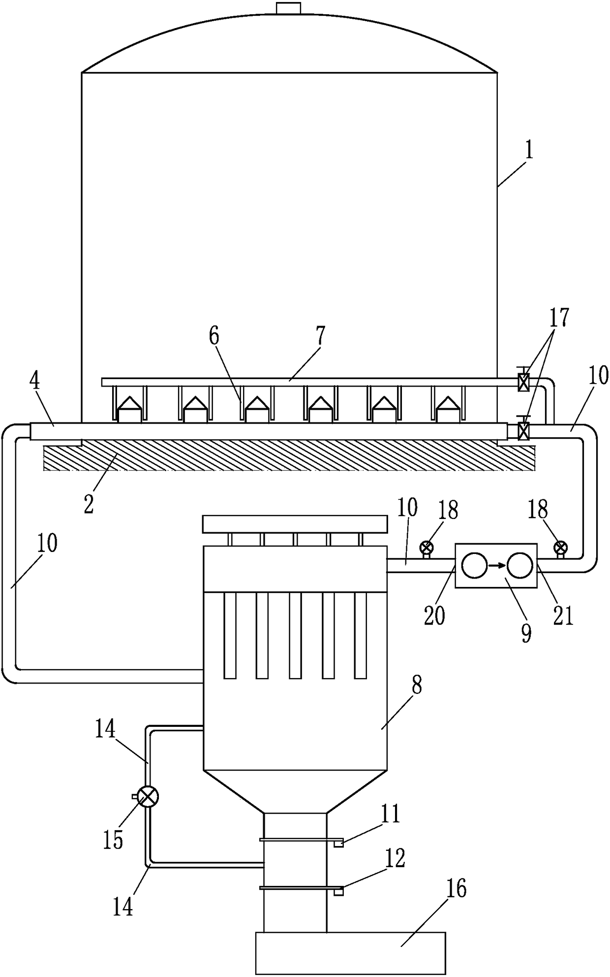
[0020] Such as figure 2 The powder storehouse shown in the present invention is equipped with an auxiliary discharge device, the difference from Embodiment 1 is that a V-shaped bevel 19 is stacked on the bottom 2 of the storehouse, and the fluidization rod 6 is arranged along the slope of the V-shaped bevel 19 , the material conveying pipe 4 is arranged at the bottom of the V-shaped groove 19; in addition, the positive pressure end of the positive and negative pressure integrated fan 9 is connected with the air supply pipeline 7 of the fluidization rod 6 through the connecting pipeline 10, which is the air supply pipeline 7 Gas supply; In addition, the discharge end of the material delivery pipe 4 is no longer provided with a material flow regulating device, and a valve for controlling the gas flow and pressure is respectively installed on the connecting pipeline 10 corresponding to the gas supply end of the material delivery pipe 4 and the gas supply pipeline 7 17; Fourth, s...


PUM


Abstract

The invention provides a powder storage warehouse provided with an auxiliary discharging device. The powder storage warehouse comprises a warehouse body, a warehouse bottom and the auxiliary discharging device, wherein a fluidization rod is arranged on the upper surface of the warehouse bottom, a fetching device is arranged on the upper surface of the warehouse bottom or in a gallery of the warehouse bottom and comprises a material conveying pipe, and the material conveying pipe extends outside the warehouse; and the auxiliary discharging device comprises a dust collector and a positive-negative pressure integrated fan, the dust collector is connected with a discharging end of the material conveying pipe and a negative pressure end of the positive-negative pressure integrated fan, respectively through a connecting pipeline, and a positive pressure end of the positive-negative pressure integrated fan is connected with an air supply end of the material conveying pipe through a connectingpipeline. The powder storage warehouse provided with the auxiliary discharging device has the beneficial effects that the structure is simple, the applicability is relatively good, and the discharging efficiency is well guaranteed.

Description

technical field [0001] The invention relates to the field of storage equipment, in particular to a large-scale fluidized powder storage for storing powder materials. Background technique [0002] At present, various large-scale fluidized storages are widely used in the storage of powder materials such as cement and fly ash because of their large storage capacity and good stability. Among them, the conveying pipe type powder bin pneumatic retrieving device (also known as material conveying pipe) recorded in the Chinese Utility Model Patent No. 201320336146.4 has simple structure, low energy consumption, few components involved, and extremely high failure rate. Low cost, basically maintenance-free, safe and reliable, and other significant advantages are widely used in the design and construction of various large-scale fluidized storage. A typical example is a floor-standing powder storage described in the Chinese invention patent No. 201310231901.7 warehouse, and a large-scal...

Claims


Application Information

Patent Timeline
Patent Type & Authority Applications(China)
IPC IPC(8): B65G53/28B65G65/40
CPCB65G53/28B65G65/40B65G2201/04
Inventor 赵世青
Owner 赵世青
Why Eureka
Try Eureka