Flow restrictor for an injector

A flow restrictor and injector technology, which is applied in fuel injection devices, special fuel injection devices, fuel injection devices with oil reservoirs, etc., can solve the problems of easy wear and tear, improve wear behavior, avoid functional interference, The effect of contact pressure peak reduction

Active Publication Date: 2018-06-08
ROBERT BOSCH GMBH
View PDF12 Cites 1 Cited by
  • Summary
  • Abstract
  • Description
  • Claims
  • Application Information

AI Technical Summary

Problems solved by technology

As a result, the edges of the contour of the bearing seat are designed to be very sharp and therefore also susceptible to wear.

Method used


Image

  • Flow restrictor for an injector
  • Flow restrictor for an injector
  • Flow restrictor for an injector

Examples


Embodiment Construction

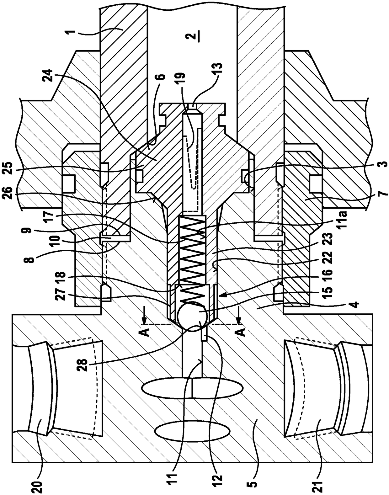
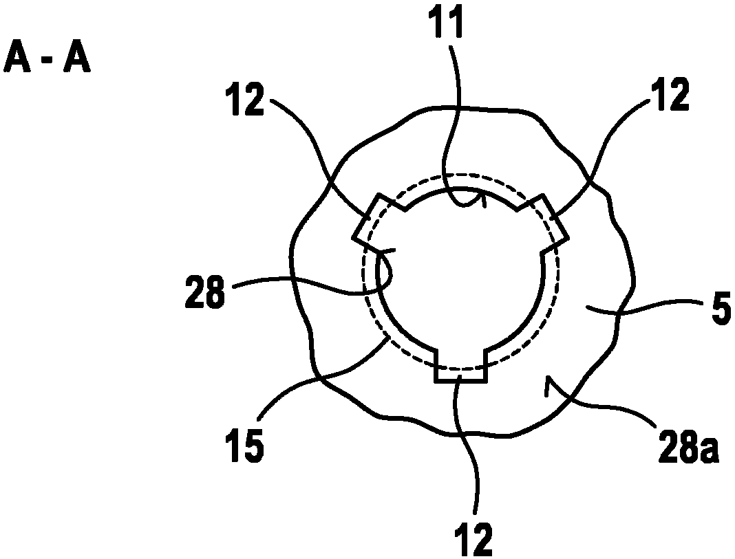
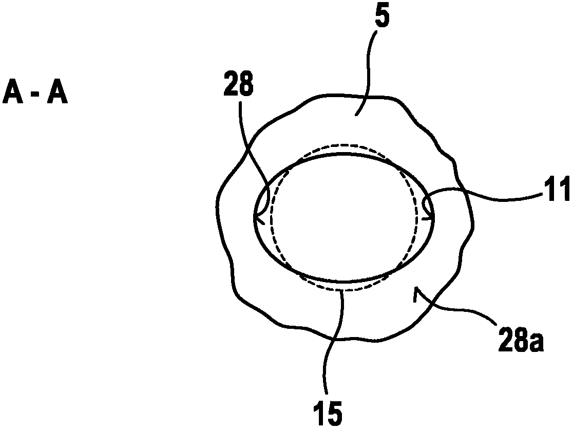
[0022] figure 1 shows the end section of the injector body 1 of the injector in which the high-pressure accumulator 2 is integrated. The injector body 1 can also be referred to as a holding body. The injector has a flow restrictor 16, wherein the flow restrictor 16 comprises a valve housing 24, an axial bore 11a formed in the valve housing 24, a ball 15 serving as a closing body and arranged in the axial bore 11a, a construction Valve seat 18 and bearing seat 28 on valve housing 24 .

[0023] The injector body or holding body 1 has an opening 3 leading to the high-pressure accumulator 2 , into which opening the screw-type section 4 of the closing screw 5 is introduced. The closing screw 5 is screwed to the injector body 1 by means of a clamping nut 7 , wherein the internal thread of the clamping nut 7 cooperates with the axially adjacent external threads of the injector body 1 and of the closing screw 5 .

[0024] A high-pressure connection 20 and a further high-pressure co...


PUM


Abstract

The invention relates to a flow restrictor (16) for an injector of a common rail fuel injection system. The flow restrictor (16) has a closure bolt (5) with a high-pressure connection (20), a valve housing (24), a ball (15), and a spring (17). A support seat (28) is formed on the closure bolt (5), and a valve seat is formed on the valve housing (24). The ball (15) is arranged in an axial bore (11a) formed in the valve housing (24) and is acted upon by the spring (17) in the direction of the support seat (28). Upon contacting the support seat (28), the ball (15) releases a hydraulic connectionof the high-pressure connection (20) through the axial bore (11a), and upon contacting the valve seat (18), the ball blocks the hydraulic connection. The support seat (28) has an oval contour.

Description

technical field [0001] The invention relates to a flow restrictor for an injector of a common rail fuel injection system, in particular a modular common rail fuel injection system. Background technique [0002] A modular common rail fuel injection system for an internal combustion engine is characterized in that part of the storage volume present in the system is present in the injector itself. Modular common rail systems are used in particularly large engines in which individual injectors may be mounted at large distances relative to each other. The sole application of one and the same rail for all injectors is meaningless in such an engine, since this rail causes violent disturbances in injection pressure during injection due to the long lines, thus resulting in longer injection durations Perceivable perturbations in the injection rate occur over time. It is therefore provided in such engines that a high-pressure accumulator is arranged within each injector. This type o...

Claims


Application Information

Patent Timeline
Patent Type & Authority Applications(China)
IPC IPC(8): F02M63/00F02M63/02F02M61/16F16K15/04
CPCF02M63/0054F02M63/0215F02M2200/18F02M2200/40F16K15/044F02M55/025
Inventor D·布拉特尔
Owner ROBERT BOSCH GMBH
Why Eureka
Try Eureka