Optical waveguide arrangement for the optical detection of drops

A technology of optical waveguide and droplet, which is preferably used in the liquid droplet discharged from the micro-metering valve to detect from the metering valve field, which can solve problems such as interference and anti-interference of electrical analog signals, achieve strong signal amplitude, and improve signal-to-noise ratio Effect

Inactive Publication Date: 2018-06-08
VERMES MICRODISPENSING GMBH
View PDF9 Cites 2 Cited by
  • Summary
  • Abstract
  • Description
  • Claims
  • Application Information

AI Technical Summary

Problems solved by technology

However, if the evaluation electronics are arranged remotely from the sensor device, the problem arises that the detected electrical analogue signals must be transmitted to the evaluation electronics in an interference-free manner
Even with this approach, disturbances based on scattered light can occur

Method used


Image

  • Optical waveguide arrangement for the optical detection of drops
  • Optical waveguide arrangement for the optical detection of drops
  • Optical waveguide arrangement for the optical detection of drops

Examples


Embodiment Construction

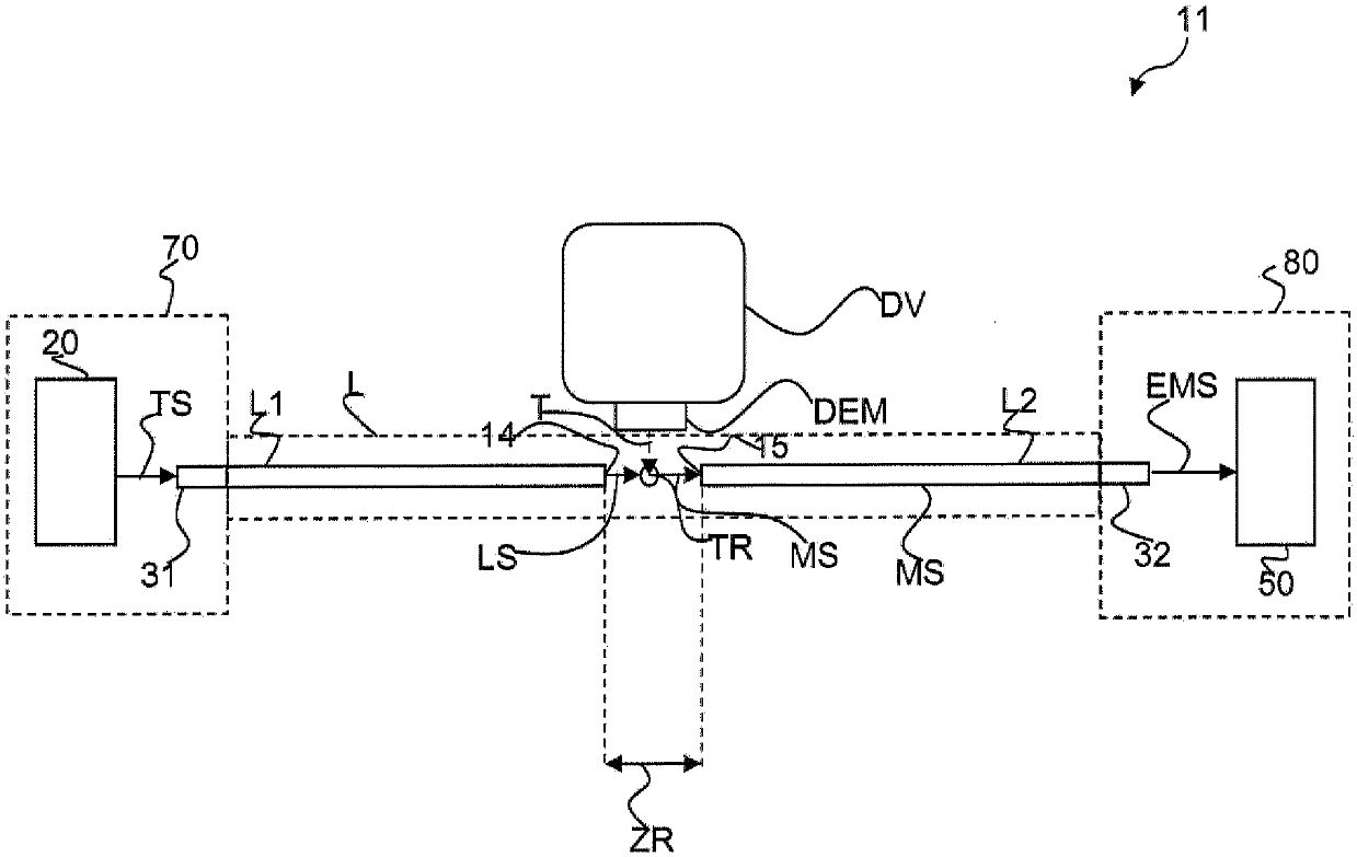
[0049] figure 1 A drop detection device 11 according to an embodiment of the present invention is shown in . in such as figure 1 In the illustrated embodiment, the liquid drop detection device 11 includes an optical signal generating device 70 , an optical waveguide unit L and an optical analysis device 80 . The optical signal generating means 70 comprise a signal generating unit 20 which generates a pulsed electrical carrier signal TS. The electrical carrier signal TS is transmitted to a light emitting unit 31, such as a light emitting diode, which converts the electrical signal TS into a light beam LS pulsed by the carrier signal TS. The pulsed light LS generated by the light emitting unit 31 is transmitted to the optical waveguide unit L. FIG. in such as figure 1 In the illustrated embodiment, the first optical waveguide element L1 of the optical waveguide unit L is connected to the light emitting unit 31 such that the light beam LS emitted from the light emitting unit ...


PUM


Abstract

Described is a drop detection apparatus (11, 11a) for detecting drops (TR) that exit a metering valve (DV) and move along a path. The drop detection apparatus (11, 11a) comprises an optical waveguidearrangement (L) having a first optical waveguide (L1) and a second optical waveguide (L2). The first optical waveguide (L1) and the second optical waveguide (L2) are arranged across from each other, in a space through which the path of the drop (TR) extends, in such a way that a light beam (LS) emitted by the first optical waveguide (L1) intersects the path (T) of the drop (TR) and is then coupledinto the second optical waveguide (L2). The drop detection apparatus (11, 11a) additionally comprises a light signal generation device (70) for coupling a light beam (LS) pulsed at a carrier frequency into the first optical waveguide (L1). The drop detection apparatus (11, 11a) further comprises a light evaluation device (80) for evaluating the light beam (LS) coupled into the second optical waveguide (L2) in order to determine whether a drop (TR) has been dispensed by the metering valve (DV). A method (500) for detecting a drop (TR) is also described.

Description

technical field [0001] The invention relates to a liquid drop detection device for detecting liquid droplets discharged from a metering valve nozzle and moving along a trajectory. Furthermore, the invention relates to a method for detecting liquid droplets discharged from a metering valve, preferably a micrometering valve. Background technique [0002] Metering valves are used in the application and metering of thin liquid or pasty media such as adhesives. The metering valve has a nozzle at the discharge point of the medium to be metered. In conventional needle valves, the opening of the metering valve is released by pulling the metering needle slightly out of the valve seat in order to meter a defined quantity of medium. In this case, for example, a medium operating under initial pressure can flow through the nozzle or valve opening. When the filling process or the metering process should be completed, the nozzle of the metering valve is closed. [0003] In particular, ...

Claims


Application Information

Patent Timeline
Patent Type & Authority Applications(China)
IPC IPC(8): G01N21/43
CPCB41J2/125G01F11/00G01F22/00G01F25/0092G01F25/10G01F11/12G01F13/006G01V8/24
Inventor 吉里·卡尔格K·W·梅勒
Owner VERMES MICRODISPENSING GMBH
Why Eureka
Try Eureka