Eureka AIR delivers breakthrough ideas for toughest innovation challenges, trusted by R&D personnel around the world.

Electrical machine comprising radial cooling slots, and wind power generation facility

A technology of radial cooling and cooling grooves, applied in wind power generation, wind turbines, cooling/ventilation devices, etc., to achieve the best utilization effect

Inactive Publication Date: 2018-06-08
FLENDER GMBH
View PDF9 Cites 3 Cited by
  • Summary
  • Abstract
  • Description
  • Claims
  • Application Information

AI Technical Summary

Problems solved by technology

So there are clear limit values ​​for the sound pressure level depending on the environment and time

Method used


Image

  • Electrical machine comprising radial cooling slots, and wind power generation facility
  • Electrical machine comprising radial cooling slots, and wind power generation facility
  • Electrical machine comprising radial cooling slots, and wind power generation facility

Examples


Embodiment Construction

[0031] In the figures, identical and functionally identical elements have the same reference signs.

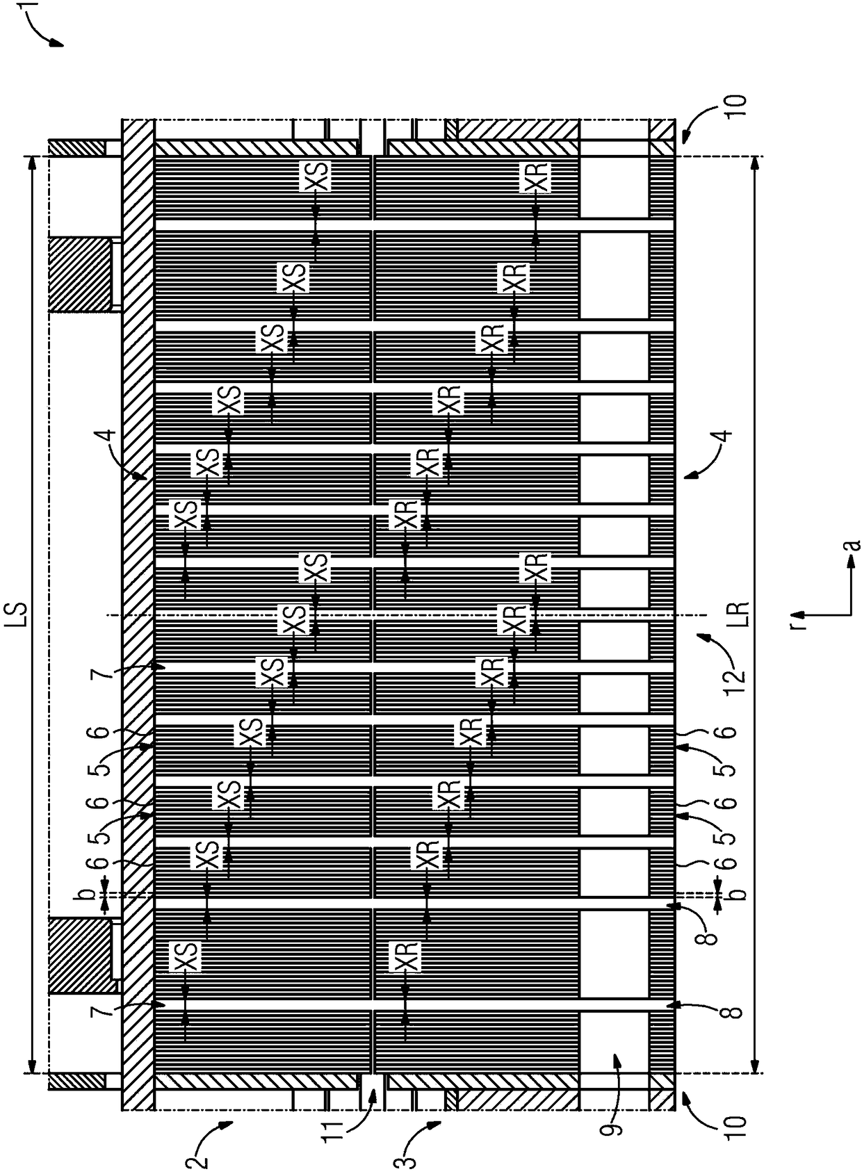
[0032] figure 1 An electric machine 1 according to the prior art is shown in a sectional side view. The electric machine 1 comprises a first active part 2 in the form of a stator. Furthermore, the electric machine 1 comprises a second active part 3 in the form of a rotor. The second active part 3 can move or rotate relative to the first active part 2 . The first active part 2 has an overall length LS in the axial direction a of the electric machine 1 and the second active part 3 has an overall length LR in the axial direction a. Currently, the total lengths LS and LR of the active parts 2, 3 are the same.

[0033] Both the first active part 2 and the second active part 3 comprise a lamination stack 4 having a plurality of individual laminations 6 . The individual laminations 6 are combined into corresponding sub-lamination groups 5 . The individual laminations 6 have an ...


PUM


Abstract

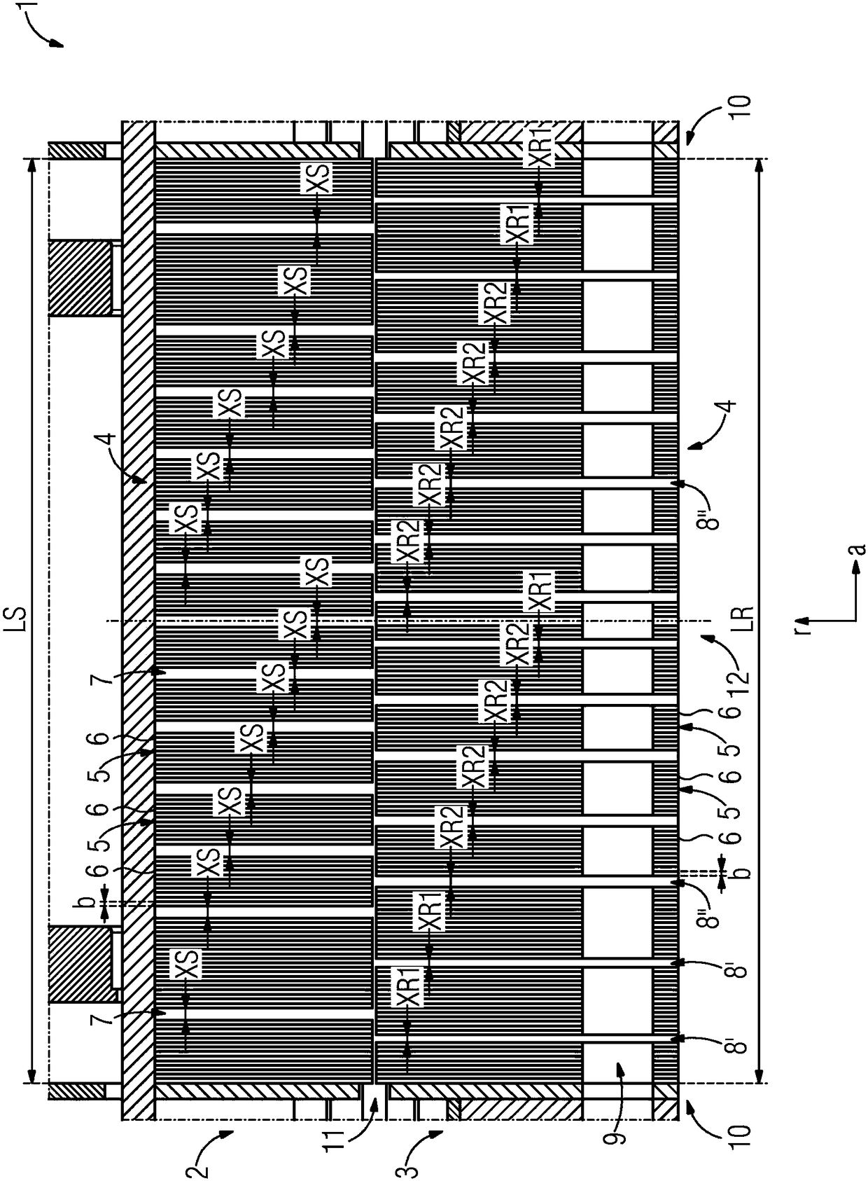
The invention relates to an electrical machine (1) comprising a first active part (2) and a second active part (3), both the first active part (2) and the second active part (3) having a plurality oflaminated sub-cores (5) and each laminated sub-core (5) having a plurality of individual laminations (6), each comprising an axial width (b). The laminated sub-cores (5) are mutually spaced in an axial direction (a) such that a respective radial cooling slot (7, 8', 8'') is formed between two adjacent laminated sub-cores (5). The radial cooling slots (7) in the first active part (2) are offset inthe axial direction (a) in relation to one another in comparison to the radial cooling slots (8', 8'') in the second active part (3), and the sum of the axial widths (b) of all individual laminations(6) in the first active part (2) corresponds to the sum of the axial widths (b) of all individual laminations (6) in the second active part (3).

Description

technical field [0001] The present invention relates to an electric machine with a first active part and a second active part, wherein the first active part and the second active part respectively comprise a plurality of sub-lamination groups, each of which includes a corresponding axial A plurality of single laminations of the width, the sub-laminations are arranged at intervals from each other in the axial direction as follows, that is, radial cooling grooves are respectively formed between two adjacent sub-laminations, and in the first active The radial cooling slots in the part are arranged staggered in the axial direction with respect to the radial cooling slots in the second active part. Furthermore, the invention relates to a wind power installation with such an electric machine. Background technique [0002] The current interest lies in an electric motor. This type of motor consists of first and second active parts or a stator and a rotor. The active part can in t...

Claims


Application Information

Patent Timeline
Patent Type & Authority Applications(China)
IPC IPC(8): H02K1/20H02K1/32
CPCH02K1/20H02K2201/15H02K1/32Y02E10/72F03D9/25F03D80/60H02K9/02H02K2201/03
Inventor 弗兰克·布拉萨斯罗伯特·格鲁贝尔马丁·克罗姆帕斯奥利弗·梅明杰克劳斯·席费雷尔托比亚斯·施佩尔罗兰·泽伊奇菲斯尔
Owner FLENDER GMBH
Why Eureka
Eureka Blog
Learn More