Rigidity-controllable positive stress electromagnetic vibration platform and control method

An electromagnetic vibration and vibration platform technology is applied in the direction of using electromagnetic means, using vibrating fluid, and using electrical devices. It can solve the problems of large power consumption, poor anti-overload ability, coil heating, etc., and achieve fast response speed and frequency band. The effect of large range and low heat generation

Active Publication Date: 2018-06-12
XI AN JIAOTONG UNIV
View PDF9 Cites 8 Cited by
  • Summary
  • Abstract
  • Description
  • Claims
  • Application Information

AI Technical Summary

Problems solved by technology

However, when the mass of the controlled object is large and it is necessary to maintain a large actuation stroke, a large current is required to generate the required output force, resulting in large power consumption and coil heating even under quasi-static conditions. serious
Due to the limitation of power consumption due to the application requirements of the vibration control object, the vibration platform based on the driving mode of the voice coil motor can only have a small overall structural rigidity, and the anti-overload ability is poor, which cannot meet the requirements of a large structural rigidity.

Method used


Image

  • Rigidity-controllable positive stress electromagnetic vibration platform and control method
  • Rigidity-controllable positive stress electromagnetic vibration platform and control method
  • Rigidity-controllable positive stress electromagnetic vibration platform and control method

Examples


Embodiment Construction

[0019] The present invention will be further described in detail below in conjunction with the drawings and specific embodiments.

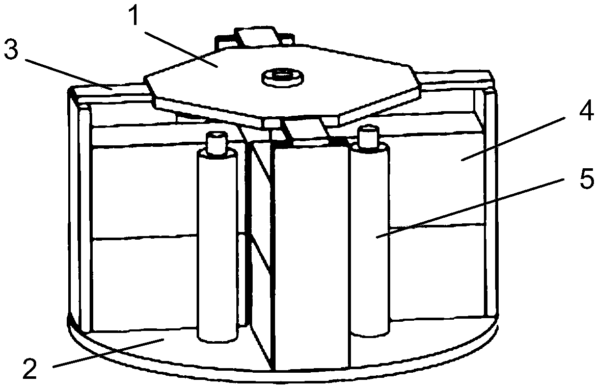
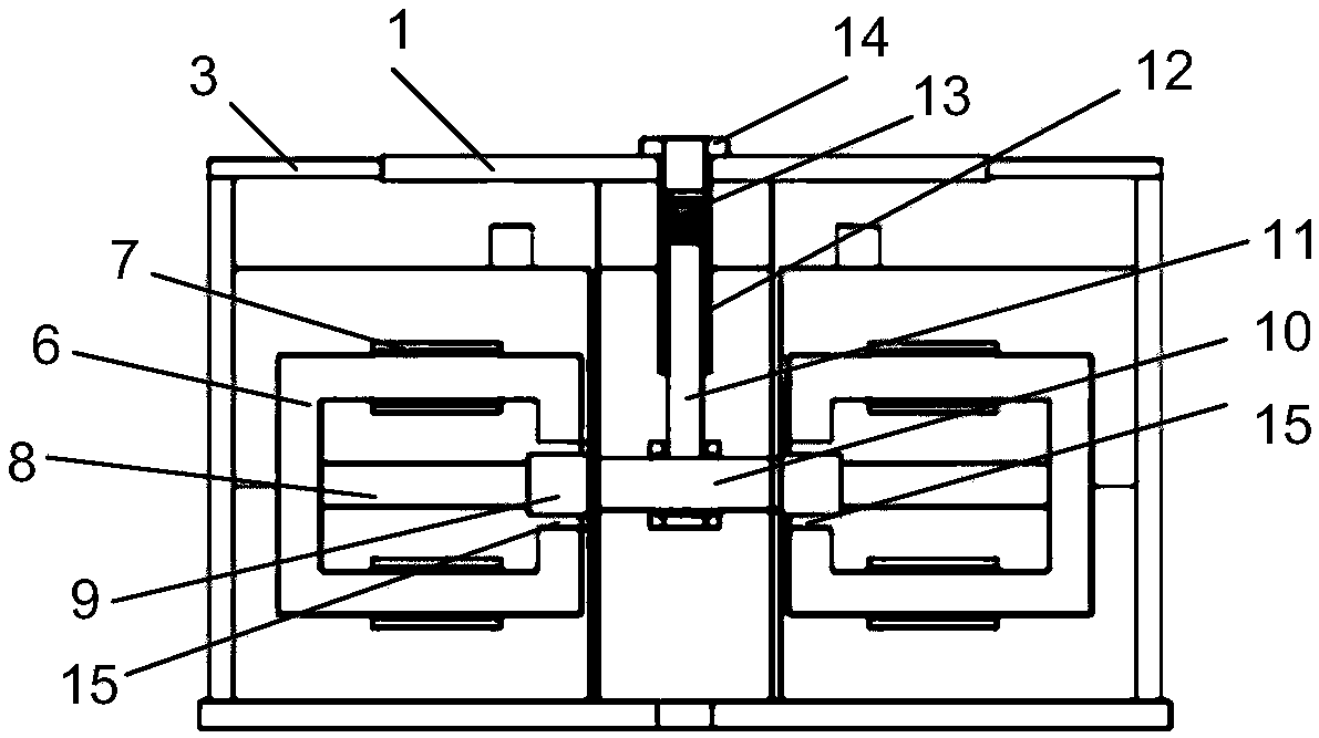
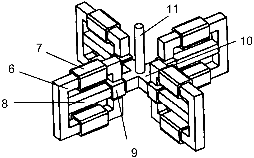
[0020] Such as figure 1 As shown, a normal stress electromagnetic vibration platform with controllable stiffness of the present invention includes a vibration platform 1 and a base 2. The vibration platform 1 is connected to the base 2 through a cantilever beam supporting structure 3. The four normal-stress electromagnetic actuators 4 are installed on the base 2 by bolts, and are arranged symmetrically around the cross-shaped mass 10, and are distributed in pairs at a diagonal angle. An actuating rod 11 is installed in the center of the cross-shaped mass 10, the actuating rod 11 is connected to the vibrating platform 1 through a spring 13, the upper end of the spring 13 is connected to the pre-tensioning device 14 that is threadedly connected to the vibrating platform 1, and the outside of the actuating rod 11 A guide sleeve 12 fixed at the lower en...


PUM


Abstract

The invention discloses a rigidity-controllable positive stress electromagnetic vibration platform and a control method. The positive stress electromagnetic vibration platform is characterized by comprising a vibration platform, a base, and a cantilever beam support structure for connecting the vibration platform with the base. The positive stress electromagnetic vibration platform further comprises positive stress electromagnetic actuators fixed between the platform and the base; a cross mass block, an actuation rod, a combination spring and a pretightening device are connected to the positive stress electromagnetic actuators in sequence; the positive stress electromagnetic actuators are symmetrically arranged around the cross mass block; and a guide sleeve is mounted at the lower end ofthe vibration platform, so that the actuation rod moves in the vertical direction along the guide sleeve. The positive stress electromagnetic vibration platform uses a capacitance displacement sensorfor monitoring vibration platform displacement signals, and uses the positive stress electromagnetic actuators for generating electromagnetic positive stress directly proportional to the vibration displacement for serial compensation of elastic force of springs to realize control of the elastic force and rigidity control of a vibration system; and the positive stress electromagnetic vibration platform is compact in structure, wide in frequency band range, convenient to install and simple in operation.

Description

Technical field [0001] The invention relates to the technical field of active and passive vibration control, and specifically designs a positive stress electromagnetic vibration platform with controllable stiffness and a control method. Background technique [0002] In the vibration engineering environment, for the control of structural vibration, it is difficult to achieve the expected control effect using passive suppression methods, and active control technology has obvious advantages over passive control for vibration suppression. As a linear drive element, the voice coil motor has a large operating stroke, no hysteresis, low drive voltage, and no transmission gap, and is widely used in active vibration control. However, when the mass of the controlled object is large and a large operating stroke needs to be maintained, a large current is required to generate the required output force, which results in large power consumption and heating of the coil even if the driving method...

Claims


Application Information

Patent Timeline
Patent Type & Authority Applications(China)
IPC IPC(8): B06B1/08G01B7/02
CPCB06B1/085G01B7/02
Inventor 张丰徐明龙马国亮田征
Owner XI AN JIAOTONG UNIV
Why Eureka
Try Eureka