Electric wheel driving system integrating steering, roll preventing and driving and control method

A drive system, integrated wheel technology, applied in steering, anti-tilt and drive integrated wheel-side electric drive system and control field, can solve the problems of three-system space and motion interference, complex structure, large space occupation, etc., to save Available space and cost, simplified system structure, good system integration effect

Active Publication Date: 2018-06-12
JILIN UNIV
View PDF10 Cites 5 Cited by
  • Summary
  • Abstract
  • Description
  • Claims
  • Application Information

AI Technical Summary

Problems solved by technology

When the traditional driving form is changed to the wheel-side driving form, there are often space and movement interference problems between the three systems, so the design of the vehicle chassis system is difficult and takes a long time
In addition, the traditional stabilizer bar in the suspension system needs to be connected to the left and right independent suspension shock absorber arms. Although it can effectively prevent the body from rolling, it also sacrifices part of the ride comfort and increases the difficulty of space layout.
Most of the existing independent anti-rolling technologies are adding anti-rolling motors for each suspension separately, which takes up a lot of space and has a complicated structure
In addition, although there is independent steering technology for each wheel, the existing independent steering technology does not consider the failure of the independent steering actuator. When the independent steering of one wheel fails, the entire vehicle cannot continue to complete the steering action. big security risk

Method used


Image

  • Electric wheel driving system integrating steering, roll preventing and driving and control method
  • Electric wheel driving system integrating steering, roll preventing and driving and control method
  • Electric wheel driving system integrating steering, roll preventing and driving and control method

Examples


Embodiment Construction

[0046] The present invention will be further described in detail below in conjunction with the accompanying drawings, so that those skilled in the art can implement it with reference to the description.

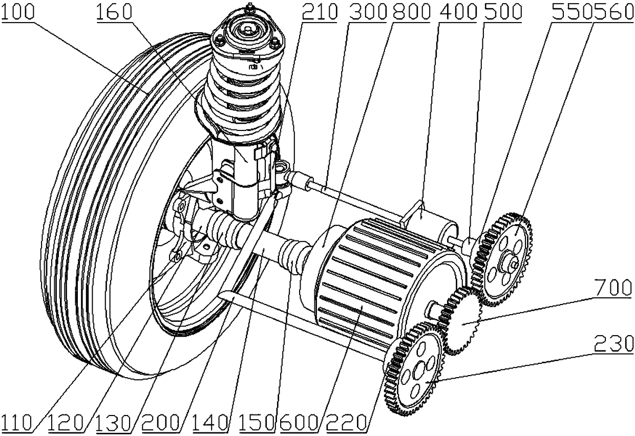
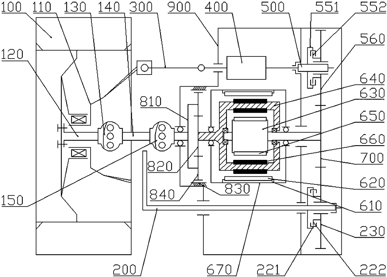
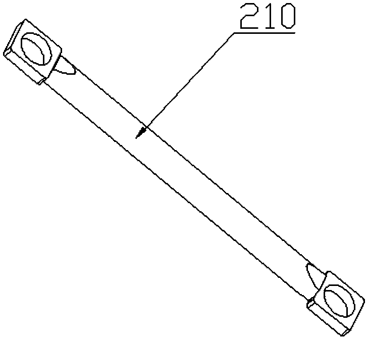
[0047] Such as Figure 1-2As shown, the present invention provides a steering, anti-roll and drive integrated wheel-side electric drive system, which includes an L-shaped anti-roll bar 200, an anti-roll connecting rod 210, a double-rotor motor 600, a linear motor 400, and a planetary gear reduction Device 800, ball screw mechanism 500, driving gear 700, steering gear 560, anti-tilt gear 230, first clutch 220, second clutch 550, steering knuckle 110, inner universal joint 150, outer universal joint 130, inner half Shaft 140 , outer half shaft 120 , tie rod 300 , shock absorber 160 and wheel drive housing 900 .

[0048] Such as figure 2 As shown, the dual-rotor motor 600 has a double-end output structure, the output end of the outer rotor 640 of the dual-rotor motor is conne...


PUM


Abstract

The invention discloses an electric wheel driving system integrating steering, roll preventing and driving. The electric wheel driving system comprises a double-rotor motor, an anti-roll gear, an L-shaped anti-roll rod and a linear motor and is characterized in that the output end of the outer rotor of the double-rotor motor is connected with a wheel, and the output end of the inner rotor of the double-rotor motor is connected with a drive gear; the anti-roll gear is located on one side of the drive gear and meshes with the drive gear; one end of the L-shaped anti-roll rod is fixedly connectedwith the anti-roll gear through a first clutch, and the other end of the L-shaped anti-roll rod is connected with a suspension; the linear motor is fixed on one side of the double-rotor motor, and the secondary end of the linear motor is connected with a steering tie rod and used for driving the steering tie rod to achieve steering; when the first clutch is in a combining state, the output end ofthe inner rotor generates resisting moment for stopping the suspension from bouncing vertically so as to prevent roll. The electric wheel driving system has the advantages that system integration isincreased, space saving is achieved, and overall-vehicle arrangement is facilitated.

Description

technical field [0001] The invention belongs to the technical field of wheel-side driving of automobiles, and in particular relates to a steering, anti-tilt and driving integrated wheel-side electric drive system and a control method. Background technique [0002] Traditional centralized drive pure electric vehicles use a powertrain consisting of a single motor and drive axle or a powertrain consisting of a single motor, transmission and drive axle to drive the vehicle. There are many transmission parts, the transmission efficiency is not high, and it takes up space. Big. [0003] The structural feature of hub drive or wheel drive is that the drive motor is directly installed in or near the drive wheel, and the motor drives the wheel directly or through a reduction mechanism. Compared with traditional cars, mechanical transmission components such as differentials are omitted, the transmission efficiency is high, the structure is compact, and the body space utilization rate ...

Claims


Application Information

Patent Timeline
Patent Type & Authority Applications(China)
IPC IPC(8): B60W10/06B60W10/20B60W10/22
CPCB60W10/06B60W10/20B60W10/22B60W2710/08Y02T10/72
Inventor 王军年罗正杨斌王凯郭德东刘培祥
Owner JILIN UNIV
Why Eureka
Try Eureka