Bushing structure of cantilever frame shock absorber
A shock absorber, suspension beam frame technology, applied in the direction of springs/shock absorbers, springs made of plastic materials, mechanical equipment, etc., can solve the problem that the bushing structure cannot bear large radial loads, and reduce development costs. and cycle, improve control flexibility, improve the effect of NVH
- Summary
- Abstract
- Description
- Claims
- Application Information
AI Technical Summary
Problems solved by technology
Method used
Image
Examples
Embodiment 1
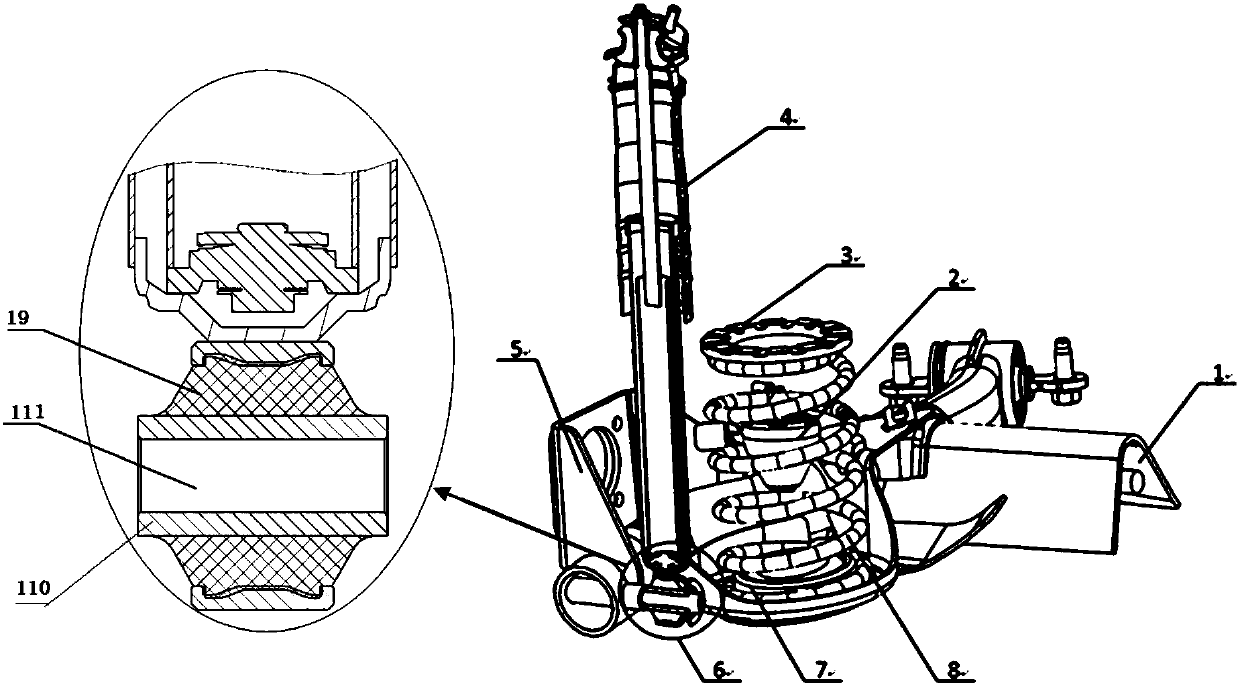
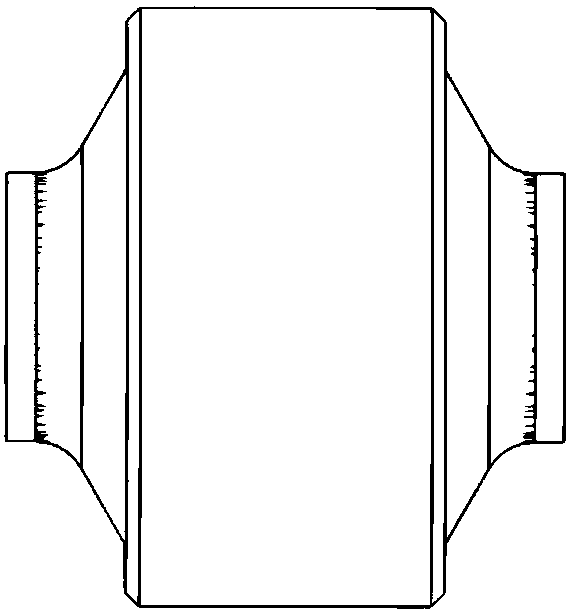
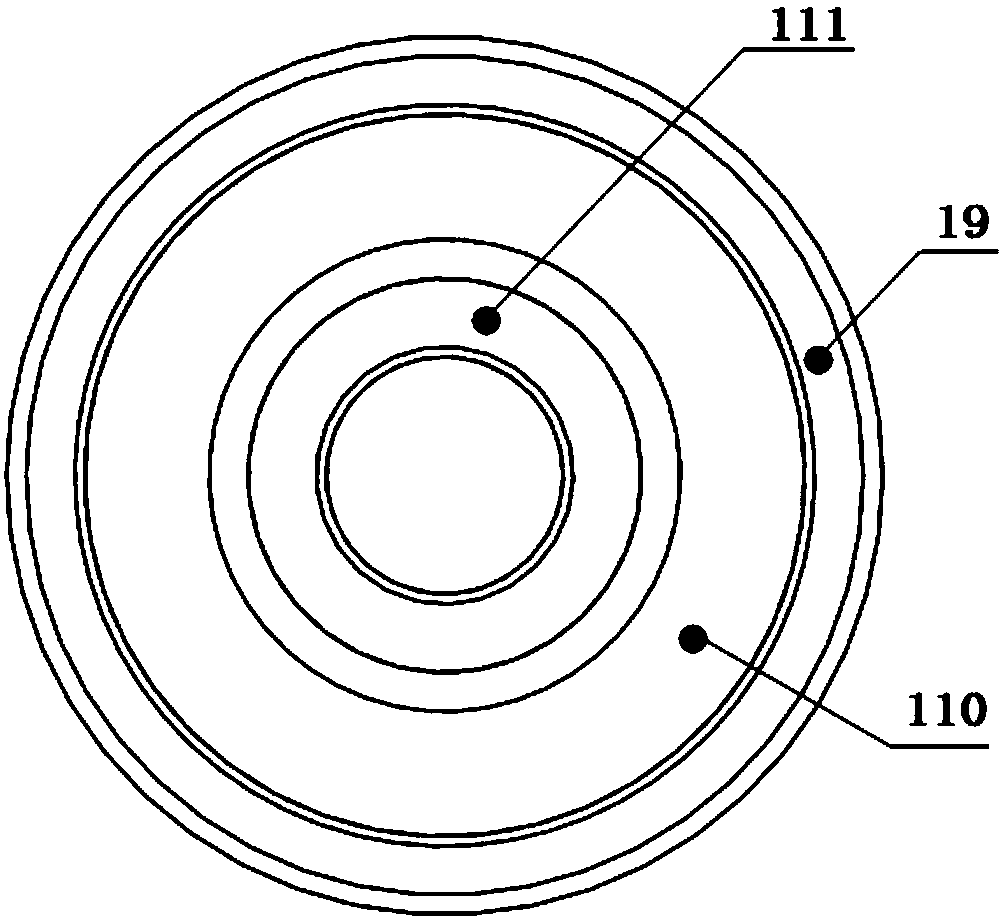
[0036] Embodiment 1, the present invention provides a suspension beam shock absorber bushing structure, which is mainly used in the suspension system on the automobile shock absorber assembly. The existing rear shock absorber lower support bushing is mainly used for transmitting force, Vibration reduction, noise reduction, motion determination, etc. The common rear shock absorber lower support bush structure mainly adopts a symmetrical structure, and there is no plug-in stopper in the axial direction. After the bolt is tightened, when the whole vehicle is running on the road, with the continuous movement of the suspension, There will be iron-iron friction at the end face of the inner steel sleeve of the vibrator bushing, resulting in abnormal noise, and the end face of the inner steel sleeve 111 of the bushing is small, which cannot withstand a large bolt torque, and is prone to torque attenuation, which is not conducive to multiple The platform vehicle type is shared, and the...
Embodiment 2
[0039] Embodiment 2, based on the above embodiments, the present invention provides a bushing structure for suspension beam shock absorbers. The difference between this embodiment and the above embodiments is that, as Figure 5 As shown, in this embodiment, in addition to adding a limit block 112 to the inner steel sleeve, a first groove 101 is added to the rubber sleeve 110, and the position of the first groove 101 is located in the On the rubber sleeve 110 between the limiting block 112 and the outer steel sleeve 19 .
[0040] Specifically, the opening of the first groove 101 is upward, and its bottom is arc-shaped, and the vulcanization part of the limiting block 112 is rounded.
[0041] Such as Figure 6 , Figure 8The dimensional drawing of the bushing structure is marked as shown, in which, the total length L1 of the bushing structure is: L1=L2+L3+(L4)+L5+L6, where L2 is the length of the mating section between the inner steel sleeve 111 and the surrounding parts (the...
Embodiment 3
[0045] Embodiment 3, based on the above embodiments, the present invention provides a bushing structure for suspension beam shock absorbers. The difference between this embodiment and the above embodiments is that, as Figure 6 As shown, the outer diameter of the outer steel sleeve 19 greater than the outer diameter of the limiting block 112 , and the outer diameter of the tail end of the inner steel sleeve 111 greater than the outer diameter of the insertion portion 113 . Such design, considering that when the bushing structure is installed into the sleeve, the diameter of the sleeve is larger than the outer diameter of the outer steel sleeve , so as to ensure that the bushing structure can be installed and disassembled smoothly. Wherein, the outer diameter φA of the limiting block 112 needs to be smaller than φE, and the length L4 between the limiting block 112 and the inner steel sleeve 111 is smaller than the length L2 of the insertion part 113 and the length L4 o...
PUM
 Abstract
Description
Claims
Application Information
 - R&D
- Intellectual Property
- Life Sciences
- Materials
- Tech Scout
- Unparalleled Data Quality
- Higher Quality Content
- 60% Fewer Hallucinations
Browse by: Latest US Patents, China's latest patents, Technical Efficacy Thesaurus, Application Domain, Technology Topic, Popular Technical Reports.
© 2025 PatSnap. All rights reserved.Legal|Privacy policy|Modern Slavery Act Transparency Statement|Sitemap|About US| Contact US: help@patsnap.com


