Heat pipe heat storage heat exchanger with pipe diameter change of communicating pipe

A heat accumulator and heat exchanger technology, applied in indirect heat exchangers, lighting and heating equipment, etc., can solve the problem that the heat exchange area cannot be better expanded, the heat absorption area of ​​the evaporation end is affected, and the heat absorption range of the evaporation end is small. and other problems, to achieve the effect of compact structure, avoid local overheating or undercooling, reduce volume and floor space

Active Publication Date: 2018-06-12
STATE GRID SHANDONG ENERGY SAVING SERVICE +2
View PDF9 Cites 9 Cited by
  • Summary
  • Abstract
  • Description
  • Claims
  • Application Information

AI Technical Summary

Problems solved by technology

[0004] In the prior art, the shape of the heat pipe affects the heat-absorbing area of ​​the evaporating end, so the heat-absorbing range of the evaporating end is generally relatively small, and sometimes it is necessary to install multiple heat pipes in the heat source to meet the heat-absorbing demand; and when there are multiple evaporating ends, Because each evaporation end is in a different position of the heat source, it will produce uneven heat absorption.
[0005] In the current heat pipe heat accumulator, gravity heat pipes are

Method used


Image

  • Heat pipe heat storage heat exchanger with pipe diameter change of communicating pipe
  • Heat pipe heat storage heat exchanger with pipe diameter change of communicating pipe
  • Heat pipe heat storage heat exchanger with pipe diameter change of communicating pipe

Examples


Embodiment Construction

[0040] The specific embodiments of the present invention will be described in detail below in conjunction with the accompanying drawings.

[0041] In this article, if there is no special explanation, when it comes to formulas, " / " means division, and "×" and "*" mean multiplication.

[0042] The specific embodiments of the present invention will be described in detail below in conjunction with the accompanying drawings.

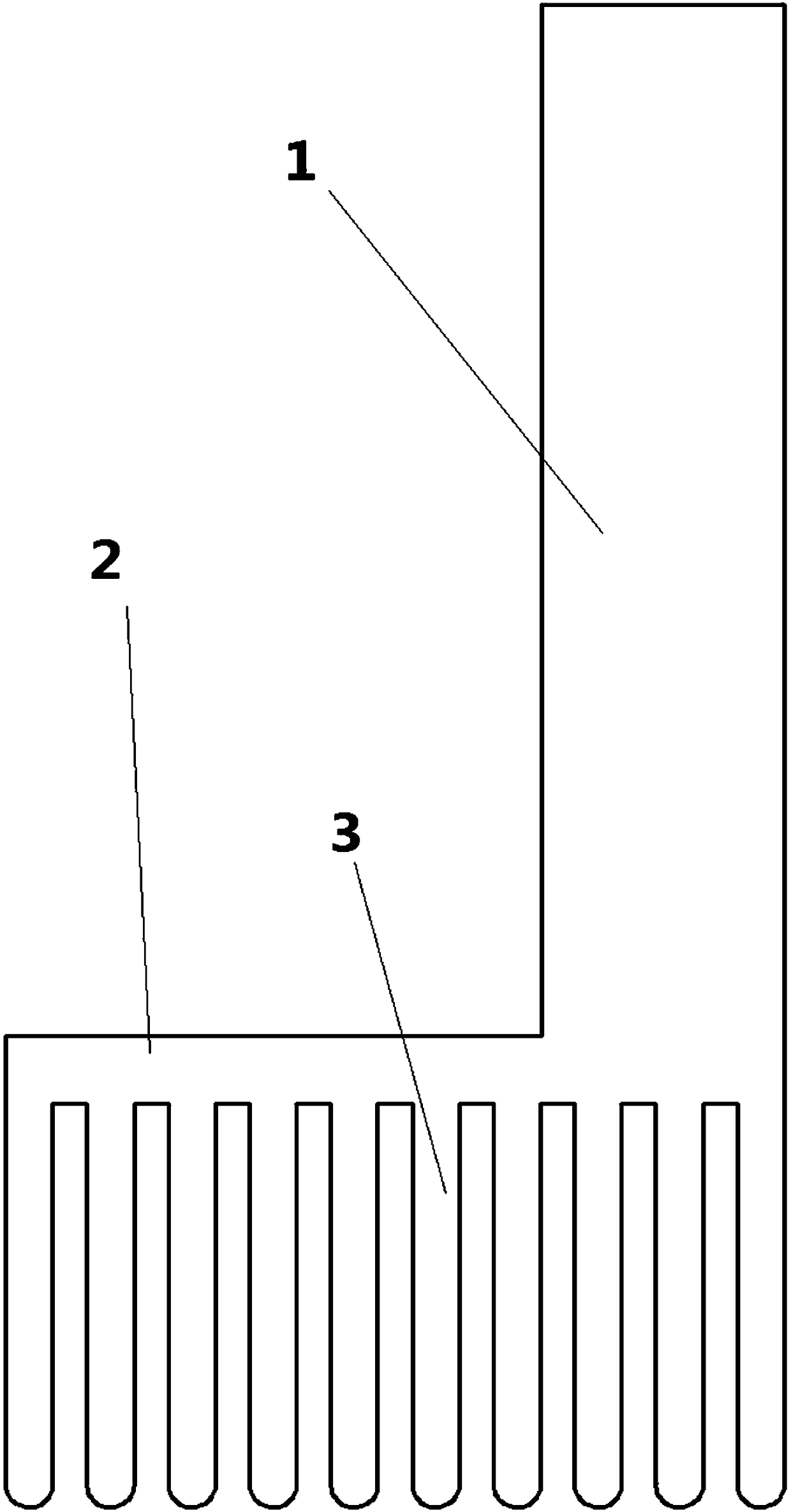
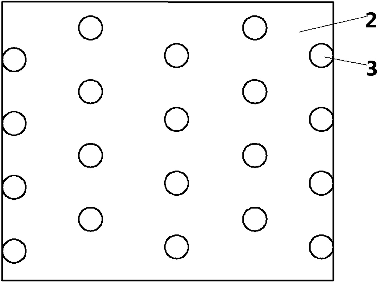
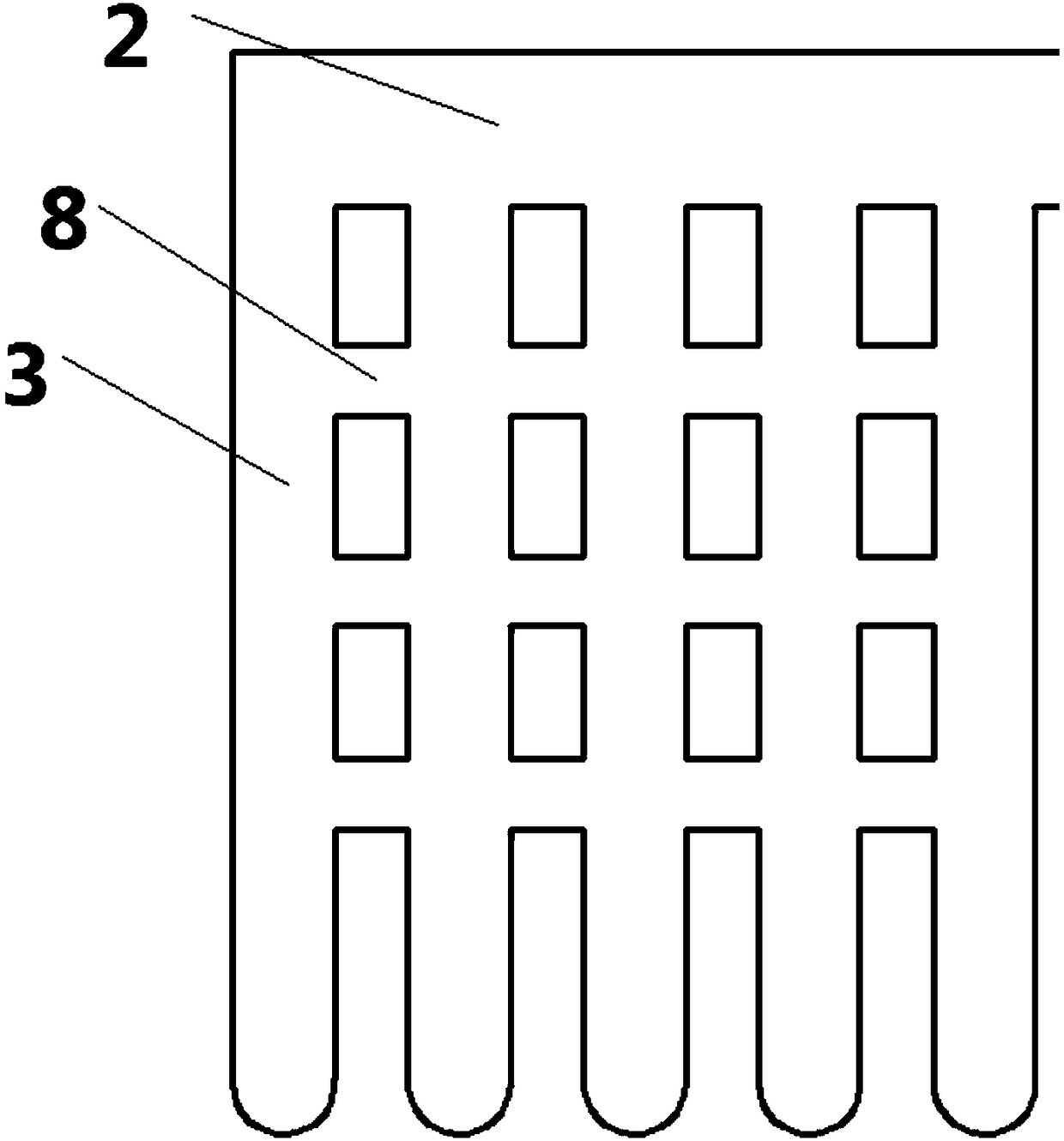
[0043] A heat pipe, comprising a vertical part 1, a horizontal part 2 and a vertical pipe 3, wherein the bottom end of the vertical part 1 communicates with the horizontal part 2, and the horizontal part 2 is from the bottom end of the vertical part 1 to the direction away from the vertical part 1, the lower part of the horizontal part 2 communicates with a plurality of vertical pipes 3, wherein the vertical pipes 3 are the evaporation end of the heat pipe, and the vertical part 1 is the condensation end of the heat pipe.

[0044] During operation, the heat ...


PUM

PropertyMeasurementUnit
Melting pointaaaaaaaaaa

Abstract

The invention provides a heat pipe heat storage heat exchanger with a pipe diameter change of communicating pipes. The heat exchanger comprises a gravity heat pipe, the heat pipe comprises an evaporation end and a condensation end; the evaporation end is arranged in a heat accumulator, and the heat accumulator is arranged in a heat source; the condensation end is arranged in a container of a coldsource, the evaporation end comprises a plurality of end parts, and the plurality of communicating pipes are arranged between every adjacent end parts; and the diameter of the communicating pipes is continuously increased in the direction from the center of the heat accumulator to the outer wall of the heat accumulator. Through the change of the pipe diameter of the communicating pipes, the pressure balance can be achieved as soon as possible in the fluid heating process.

Description

technical field [0001] The invention relates to a heat exchanger technology, in particular to a heat pipe heat storage heat exchanger. Background technique [0002] Heat pipe technology is a heat transfer element called "heat pipe" invented by George Grover of Los Alamos National Laboratory in the United States in 1963. It makes full use of the principle of heat conduction and phase change medium. The rapid heat transfer properties of the heat pipe quickly transfer the heat of the heating object to the heat source, and its thermal conductivity exceeds that of any known metal. [0003] Heat pipe technology was widely used in aerospace, military and other industries before. Since it was introduced into the radiator manufacturing industry, people have changed the traditional radiator design ideas and got rid of the single heat dissipation mode that only relies on high air volume motors to obtain better heat dissipation. The use of heat pipe technology enables the radiator to o...

Claims


Application Information

Patent Timeline
IPC IPC(8): F28D15/02
CPCF28D15/0275
Inventor 卞峰牛蔚然马俊迪朱国梁樊相臣魏姗姗陈书祥刘建文张雪缘吕雯李燕王永彬李宏刘宗杰周建全董文秀李维秦贞依李一真冷学礼邱燕田茂诚张冠敏
Owner STATE GRID SHANDONG ENERGY SAVING SERVICE
Why Eureka
Try Eureka