A Design Method of Diffractive Optical Element Based on Spatial Partial Coherent Light

A technology of diffractive optical elements and design methods, applied in the field of diffractive optics, can solve problems such as affecting imaging quality, and achieve the effect of enhancing image quality and suppressing speckle

Active Publication Date: 2019-07-30
BEIJING INSTITUTE OF TECHNOLOGYGY
View PDF4 Cites 1 Cited by
  • Summary
  • Abstract
  • Description
  • Claims
  • Application Information

AI Technical Summary

Problems solved by technology

[0005] The present invention provides a design method and device for a diffractive optical element in order to solve the problem in the prior art that the random ebb and flow of coherent light affects the imaging quality

Method used


Image

  • A Design Method of Diffractive Optical Element Based on Spatial Partial Coherent Light
  • A Design Method of Diffractive Optical Element Based on Spatial Partial Coherent Light
  • A Design Method of Diffractive Optical Element Based on Spatial Partial Coherent Light

Examples


Embodiment Construction

[0021] The specific implementation manners of the present invention will be further described in detail below in conjunction with the accompanying drawings and embodiments. The following examples are used to illustrate the present invention, but are not intended to limit the scope of the present invention.

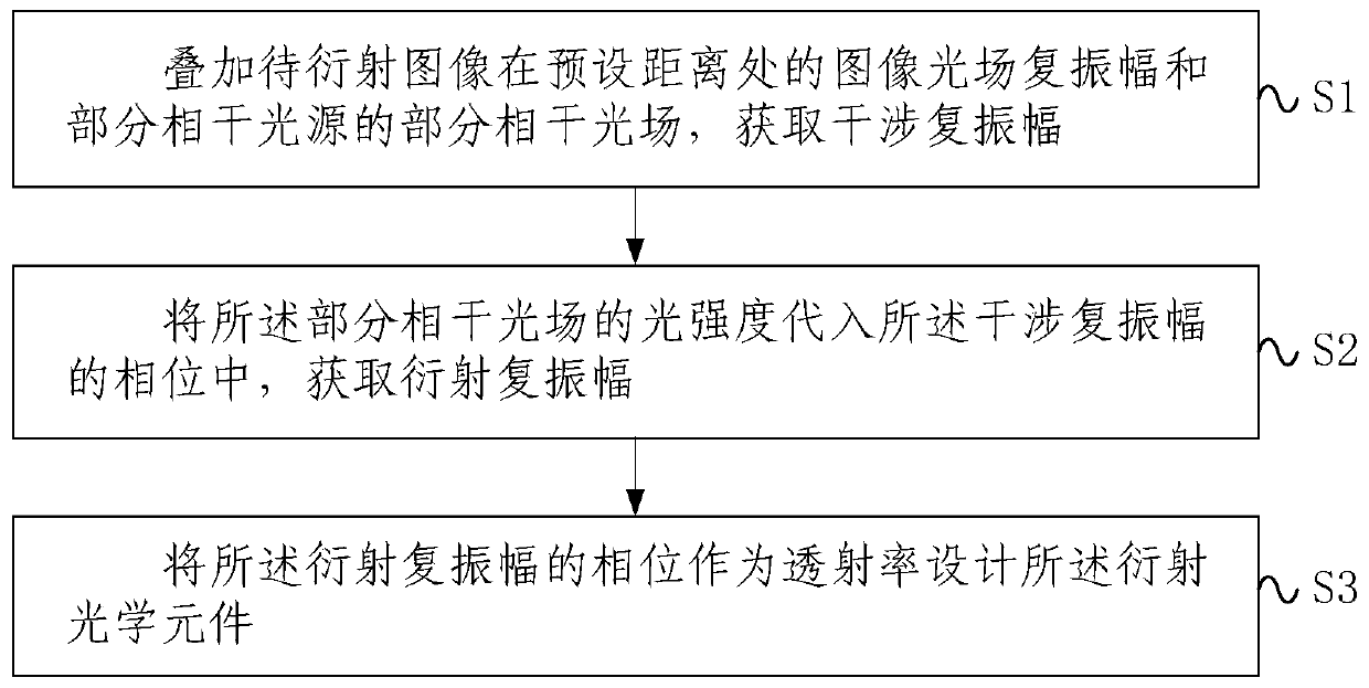
[0022] figure 1 It is a schematic flow chart of a design method of a diffractive optical element according to a specific embodiment of the present invention, such as figure 1 As shown, a design method of a diffractive optical element includes: S1, superimposing the complex amplitude of the image light field of the image to be diffracted at a preset distance and the partially coherent light field of the partially coherent light source to obtain the interference complex amplitude; S2, the Substituting the light intensity of the partially coherent light field into the phase of the interference complex amplitude to obtain the diffraction complex amplitude; S3, using the phase...


PUM


Abstract

The invention provides a method and device for designing a diffractive optical element. The method comprises the steps of S1, superposing the image light field complex amplitude of an image to be diffracted at a preset distance and the partially coherent light field of a partially coherent light source to obtain the interference complex amplitude; S2, substituting the light intensity of the partially coherent light field into the phase of the interference complex amplitude to obtain the diffractive complex amplitude; and S3, enabling the phase of the diffractive complex amplitude to serve as the transmittance to design the diffractive optical element. According to the method and device provided by the invention for designing the diffractive optical element, the characteristics that the coherent part of the partially coherent light can be coded and modulated and a non-coherent part of the partially coherent light can be averagely speckled are applied to the field of diffractive opticalelement design, a phenomenon of random rise and elimination of the light field amplitude is weakened while wavefront modulation is achieved, the speckles are suppressed, and the image quality is enhanced.

Description

technical field [0001] The invention relates to the technical field of diffractive optics, in particular to a design method and device for a diffractive optical element. Background technique [0002] Diffractive optical element is a new type of optical element with important application prospects. Its design is based on the theory of optical diffraction, and the kinoform is designed by computer and manufactured by microelectronic processing technology, so that it can finally realize several optical functions at the same time. [0003] The design method of traditional diffractive optical elements is based on the premise of coherent light. During the optical modulation process, random constructs and phases will appear, which will lead to speckle in the modulation result and affect the imaging quality. To solve this problem, iterative algorithms, time multiplexing, coherent recording, non-coherent reproduction, and pixel separation methods can usually be used to average the ran...

Claims


Application Information

Patent Timeline
Patent Type & Authority Patents(China)
IPC IPC(8): G02B27/00G06F17/50
CPCG02B27/0012G06F30/17
Inventor 刘娟段俊毅
Owner BEIJING INSTITUTE OF TECHNOLOGYGY
Why Eureka
Try Eureka