
Virtual joystick control method and system based on gyroscope as well as medium and equipment thereof

A technology of virtual joystick and control method, applied in the field of gyroscope-based virtual joystick control method and device and its medium and terminal, which can solve the problems of incomparable complexity and accuracy, inability to quickly and real-time control the zero point, and no disclosure Zero state and other issues to achieve the effect of saving space, convenient gesture operation, and easy to carry

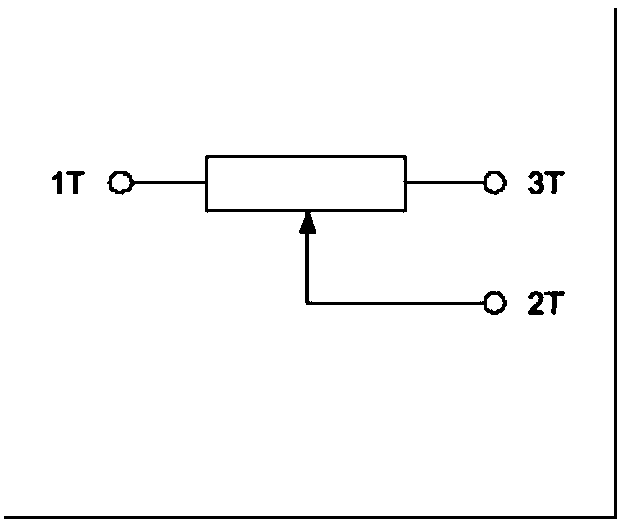
Active Publication Date: 2018-06-15
上海感悟通信科技有限公司 +1
View PDF9 Cites 5 Cited by
  • Summary
  • Abstract
  • Description
  • Claims
  • Application Information

AI Technical Summary

Problems solved by technology

Although somatosensory controllers such as Wii also use motion control instead of mechanical 3D joystick control, and change the operations that must be done with fingers to arm and body, it can be considered that certain joystick characteristics are achieved. However, due to the somatosensory The one-handed operation of the controller makes it unable to meet the needs of games that require complex operations with multiple buttons. Therefore, when the motion controller is used as a general-purpose handle, it is necessary to configure a two-handed controller with separated hands. Even so, the motion controller still cannot control the game. Equivalent to the complexity and precision of a general-purpose gamepad in the game
[0008] Further, although the above-mentioned patent document CN103111073A discloses that the zero point state needs to be set, and then the coordinate system is set according to the zero point state, the patent document CN103111073A does not disclose how to set the zero point state, and the zero point cannot be controlled quickly and in real time, resulting in the simple function of the virtual joystick

Method used


Image

  • Virtual joystick control method and system based on gyroscope as well as medium and equipment thereof
  • Virtual joystick control method and system based on gyroscope as well as medium and equipment thereof
  • Virtual joystick control method and system based on gyroscope as well as medium and equipment thereof

Examples


Embodiment Construction

[0068] The present invention will be described in detail below in conjunction with specific embodiments. The following examples will help those skilled in the art to further understand the present invention, but do not limit the present invention in any form. It should be noted that those skilled in the art can make several changes and improvements without departing from the concept of the present invention. These all belong to the protection scope of the present invention.

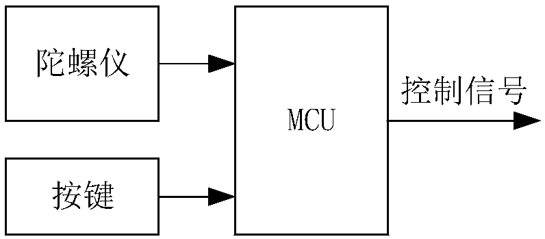
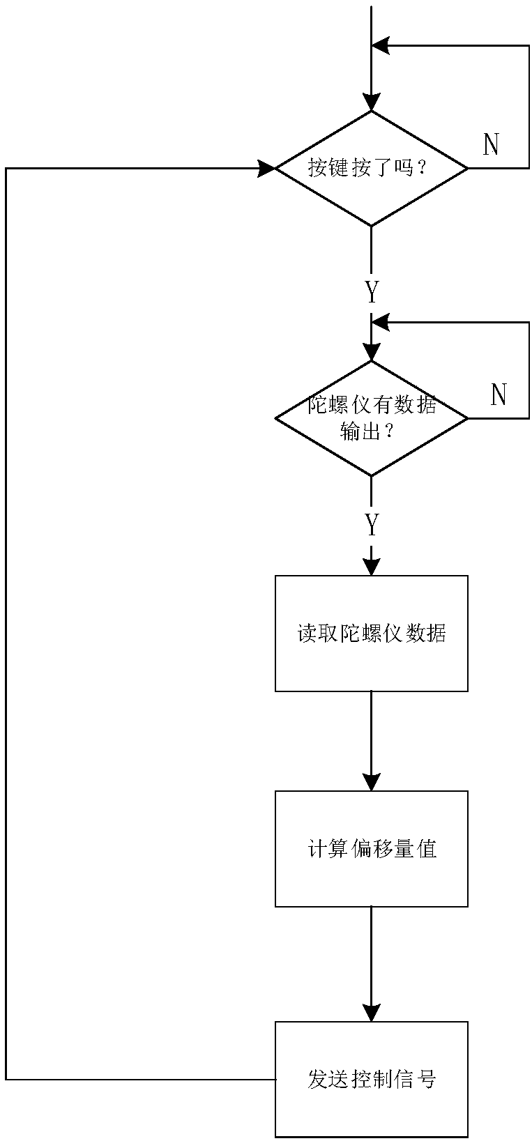
[0069] According to a kind of gyroscope-based virtual rocker control method provided by the present invention, comprising:

[0070] Origin trigger step: real-time detection of origin trigger instructions formed by the operation keys being triggered;

[0071] Origin setting step: set the origin state according to the current state of the gyroscope when the origin trigger command is received;

[0072] Offset processing step: Obtain the amount of change between the real-time state of the gyroscope and the...


PUM


Abstract

The invention provides a virtual joystick control method, a control system and control equipment based on a gyroscope, and a medium. The control method comprises the following steps: detecting an original-point trigger instruction which is formed when an operating key is triggered in real time; setting an original-point state in accordance with the current state of the gyroscope when the original-point trigger instruction is received; and acquiring a variable quantity between the real-time state of the gyroscope and the original-point state, obtaining offset of a virtual joystick. According tothe invention, the gyroscope, in coordination with such operating key as physical keys and the like, can solve a problem on original point well, and the gyroscope, when used for operating and controlling unmanned aerial vehicles, remote control vehicles, electronic games and the like, is quite convenient; in addition, the virtual joystick is small in size and operating space and convenient to carry; and the virtual joystick can be compatible with user terminals such as an existing smart phone and the like, so that an additional virtual joystick is achieved.

Description

technical field [0001] The present invention relates to the field of virtual joystick control, in particular to a gyroscope-based virtual joystick control method and device as well as its medium and terminal. Background technique [0002] At present, the game console industry is in the ascendant, and new game experiences combined with VR and AR technologies are emerging in an endless stream. Quite a few of these consoles require physical controls, usually via joysticks. [0003] Taking the patent document CN202015480U as an example, the patent document CN202015480U discloses a gamepad, which includes a travel button arranged on the housing, and detects the analog value corresponding to the press of the travel button through a potentiometer, and then communicates with the potential through a processing unit. The device is electrically connected and converts and processes the analog quantity. These handle devices generally include joysticks, which are used to more accurately...

Claims


Application Information

Patent Timeline
IPC IPC(8): A63F13/211A63F13/42
CPCA63F13/211A63F13/42A63F2300/105
Inventor 姚海平司宏伟
Owner 上海感悟通信科技有限公司
Learn More