Concrete batching device

A concrete and discharge pipe technology, which is applied in the direction of clay preparation equipment, cement mixing equipment, chemical instruments and methods, etc., can solve the problems of spraying grout ratio, uneven mixing, dust generation, and many manpower

Inactive Publication Date: 2018-06-15
马鞍山市鑫叶节能科技有限公司
View PDF6 Cites 3 Cited by
  • Summary
  • Abstract
  • Description
  • Claims
  • Application Information

AI Technical Summary

Problems solved by technology

In this process, a lot of physical labor is consumed, and the proportioning and mixing of the sprayed grout are not uniform, and dust is generated
From the above description, it can

Method used


Image

  • Concrete batching device
  • Concrete batching device
  • Concrete batching device

Examples


Embodiment 1

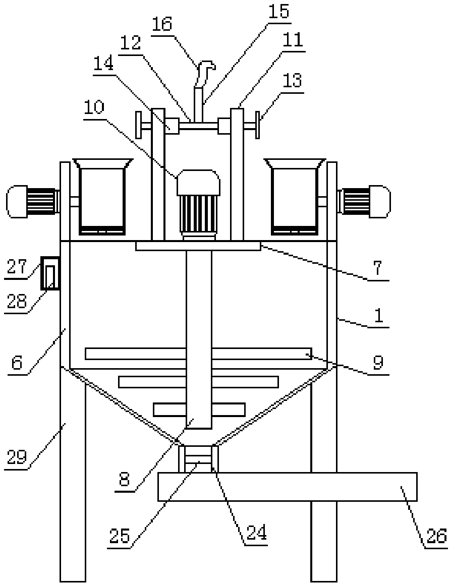
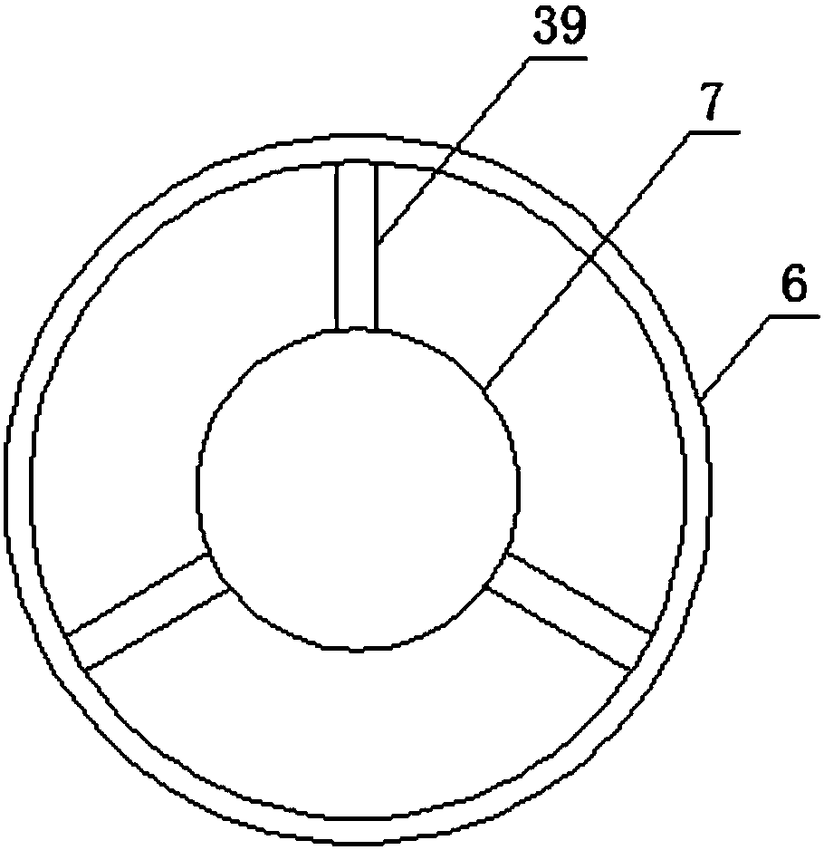
[0017] Embodiment 1: refer to Figure 1-3 , a concrete batching device, including a mixing mechanism 1, the mixing mechanism 1 includes a mixing drum 6, the top of the mixing drum 6 is provided with a fixed circular plate 7, and the fixed circular plate 7 is provided with a rotating rod 8 , the rotating rod 8 is provided with a stirring blade 9, the top of the fixed circular plate 7 is provided with a first motor 10, the rotating rod 8 runs through the fixed circular plate 7 and is connected to the first motor 10 in transmission, the first Both sides of the motor 10 are provided with fixed straight rods 11, the fixed straight rods 11 are provided with a first dust discharge pipe 12, the end of the first dust discharge pipe 12 is provided with a suction head 13, and the first row of The dust pipe 12 is provided with a blower 14, the top of the first dust discharge pipe 12 is provided with a second dust discharge pipe 15, and the top of the second dust discharge pipe 15 is provi...

Embodiment 2

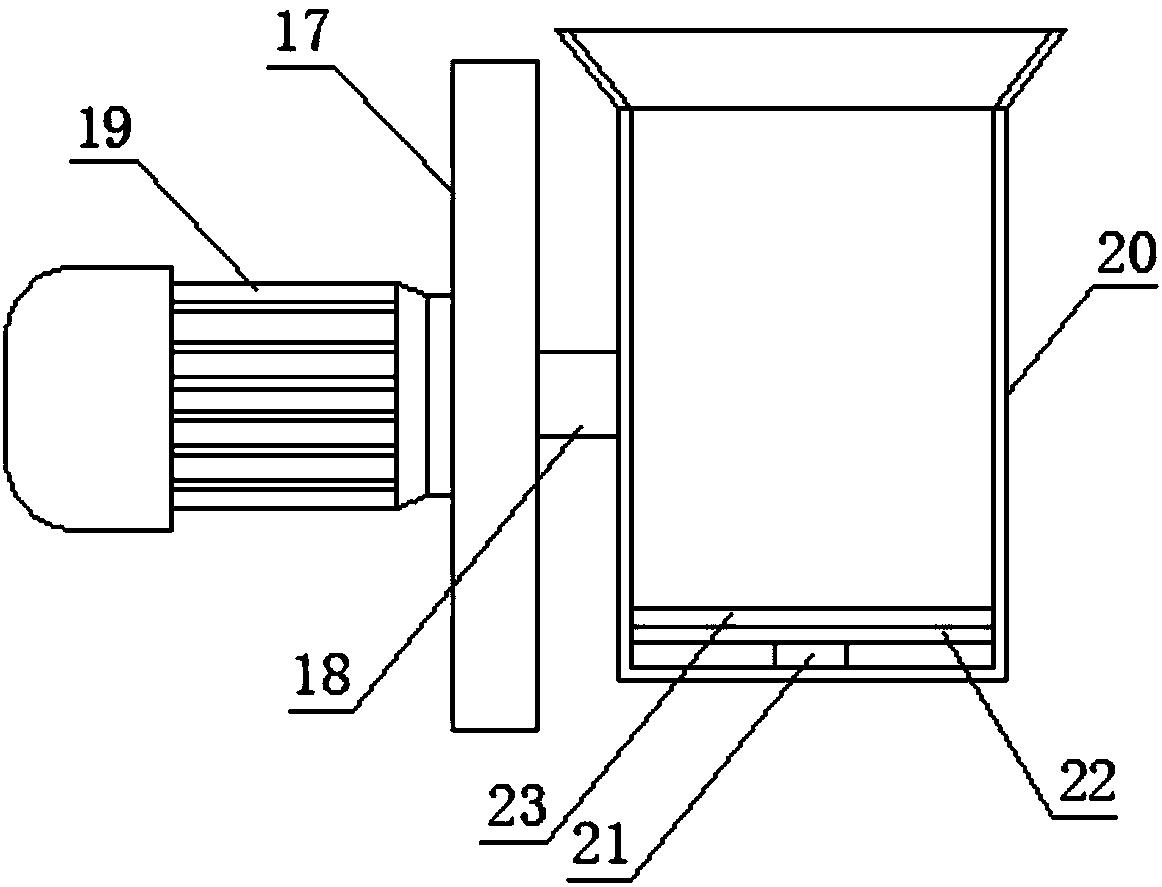
[0020] Embodiment 2: refer to Figure 2-4 , applying the present invention to a concrete batching device, one side of the mixing mechanism 1 is provided with a first chute 2 and the other side is provided with a second chute 3, and one side of the first chute 2 is provided with a first Processing mechanism 4, a second processing mechanism 5 is provided on one side of the second chute 3, the mixing mechanism 1 includes a mixing drum 6, the top of the mixing drum 6 is provided with a fixed circular plate 7, and on the fixed circular plate 7 A rotating rod 8 is installed through, and a stirring blade 9 is arranged on the rotating rod 8. A first motor 10 is arranged on the top of the fixed circular plate 7. The rotating rod 8 penetrates the fixed circular plate 7 and is transmitted with the first motor 10. connection, both sides of the first motor 10 are provided with a fixed straight rod 11, the fixed straight rod 11 is provided with a first dust discharge pipe 12, and the end of...


PUM


Abstract

The invention discloses a concrete batching device. The concrete batching device comprises a mixing mechanism. The mixing mechanism comprises a mixing drum. A fixing circular plate is arranged at thetop of the mixing drum. A rotary rod is arranged on the fixing circular plate in a penetrating mode. Mixing vanes are arranged on the rotary rod. A first motor is arranged at the top of the fixing circular plate. The rotary rod penetrates through the fixing circular plate and is in transmission connection with the first motor. Fixing straight bars are arranged on the two sides of the first motor correspondingly. A first dust flue is arranged on the fixing straight bars in a penetrating mode. Suction heads are arranged at the ends of the first dust flue. An air blower is arranged on the first dust flue. A second dust flue is arranged at the top of the first dust flue. A water bath connecting pipe is arranged at the top end of the second dust flue. Compared with traditional manual work, theconcrete batching device is high in automation degree, labor output is effectively reduced, dust produced in the processing process is effectively treated, meanwhile, weighing results are more accurate than results of manual weighing, and thus the quality of processed concrete is ensured.

Description

technical field [0001] The invention relates to the technical field of concrete construction equipment, in particular to a concrete batching device. Background technique [0002] At present, in the construction process of tunneling roadway and pioneering rock roadway in coal mines, anchor shotcrete support is mostly used, and the anchor rod, shotcrete and surrounding rock jointly form a bearing structure, which restricts the free development of surrounding rock deformation and prevents the rock mass from loosening and falling. To achieve the purpose of maintaining roadway safety. Among them, before the concrete spraying, the concrete raw materials need to be transported to the underground, and through a series of direct manpower operations, the preparation process generally includes the following steps. The specific process is as follows: Use 2 people to use a shovel to shovel the two materials from the mine car to another container in proportion, and then use at least 1 pe...

Claims


Application Information

Patent Timeline
IPC IPC(8): B28C5/16
CPCB28C5/16
Inventor 叶伟
Owner 马鞍山市鑫叶节能科技有限公司
Why Eureka
Try Eureka