Eureka AIR delivers breakthrough ideas for toughest innovation challenges, trusted by R&D personnel around the world.

Vehicle congestion region control method and device

A technology for area control and vehicle congestion, applied in control devices, vehicle components, hybrid vehicles, etc., can solve problems such as deterioration of fuel utilization, reduce the possibility of deterioration of fuel utilization, reduce charging times, and prolong service life Effect

Active Publication Date: 2018-06-15
ZHEJIANG GEELY AUTOMOBILE RES INST CO LTD +1
View PDF6 Cites 9 Cited by
  • Summary
  • Abstract
  • Description
  • Claims
  • Application Information

AI Technical Summary

Problems solved by technology

[0007] In view of this, the object of the present invention is to provide a method and device for controlling vehicle congestion areas, so as to improve the problem that the vehicle repeatedly charges the high-voltage battery forcibly under congestion conditions, resulting in deterioration of fuel utilization rate.

Method used


Image

  • Vehicle congestion region control method and device
  • Vehicle congestion region control method and device
  • Vehicle congestion region control method and device

Examples


no. 1 example

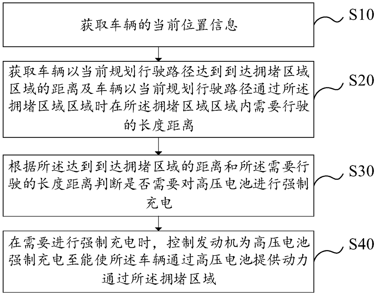
[0034]This embodiment provides a method for controlling a vehicle congestion area, please refer to figure 1 , figure 1 A flow chart of the method for controlling a vehicle congestion area provided by this embodiment is shown.

[0035] The vehicle congestion area control method includes the following steps:

[0036] Step S10: Obtain the current location information of the vehicle.

[0037] After the vehicle is started, it searches through the Internet of Vehicles service platform to see whether there is a traffic jam area. The traffic flow cannot go smoothly, and more than part of the traffic flow is stranded on the road; at the same time, the current location of the vehicle is obtained through the vehicle's own positioning system and the Internet of Vehicles service platform. Optionally, in this embodiment, The positioning system may be a GPS positioning system or a Beidou positioning system, which is not limited in this embodiment.

[0038] Step S20: Obtain the distance f...

no. 2 example

[0073] This embodiment provides a vehicle congestion area control device 100 .

[0074] It should be noted that the basic principles and technical effects of the vehicle congestion area control device 100 provided by this embodiment are basically the same as those of the first embodiment. For a brief description, the parts not mentioned in this embodiment can be referred to Corresponding content in the above-mentioned first embodiment.

[0075] see Figure 4 , Figure 4A schematic diagram of functional modules of the vehicle congestion area control device 100 is shown. The vehicle congestion area control device 100 includes a location acquisition module 110 , a distance acquisition module 120 , a judgment module 130 and a charging module 140 .

[0076] The position obtaining module 110 is used to obtain the current position information of the vehicle. The current location of the vehicle is determined by the positioning system of the vehicle. It can be understood that the l...


PUM


Abstract

The invention provides a vehicle congestion region control method and device and relates to the technical field of new-energy automobiles. The method includes the steps that current position information of a vehicle is obtained; the distance before the vehicle reaches a congestion region and the distance of the vehicle traveling in the congestion region when the vehicle passes the congestion region are obtained; according to the distance before the vehicle reaches the congestion region and the distance at which the vehicle needs to travel, whether a high-voltage battery needs to be forcibly charged or not is judged; and when the high-voltage battery needs to be forcibly charged, an internal combustion engine is controlled to forcibly charge the high-voltage battery until the vehicle can besupplied with power through the high-voltage battery so as to pass the congestion region. By the adoption of the provided vehicle congestion region control method and device, power consumption of thevehicle is estimated in advance, the high-voltage battery is charged before the vehicle enters the congestion region, the possibility that when the vehicle travels in the congestion region, the high-voltage battery is repeatedly forcibly charged due to the fact that the electric quantity of the high-voltage battery reaches the lower limit, and the fuel use rate is reduced is avoided, the number of times of charging is reduced, and the service life of the high-voltage battery is prolonged.

Description

technical field [0001] The invention relates to the technical field of new energy vehicles, in particular to a method and device for controlling a vehicle congestion area. Background technique [0002] A hybrid vehicle is equipped with an internal combustion engine as a driving source of the vehicle, an electric motor as a driving source of the vehicle, and a high-voltage battery that supplies electric power to the electric motor. mode), or the motor alone can drive the vehicle to run (hereinafter referred to as EV mode). The electric motor can be used for regenerative braking, and electric power generated by the regenerative braking can be charged to the high-voltage battery, and electric power generated using the output of the internal combustion engine can be charged to the high-voltage battery. [0003] Generally, when the output power of the internal combustion engine is small, the operating efficiency of the internal combustion engine is low. When the vehicle starts ...

Claims


Application Information

Patent Timeline
Patent Type & Authority Applications(China)
IPC IPC(8): B60W20/15B60W20/13B60W10/06B60W10/26B60W40/04
CPCB60W10/06B60W10/26B60W20/13B60W20/15B60W40/04B60W2510/244B60W2540/00B60W2554/00B60W2710/06B60W2710/244
Inventor 陈雪丽阮鸥蓝晓东
Owner ZHEJIANG GEELY AUTOMOBILE RES INST CO LTD
Why Eureka
Eureka Blog
Learn More