
Crank-arm steel dam gate

A technology of steel dams and curved arms, which is applied in the dam structure field of water conservancy facilities, can solve the problems of affecting the service life of lifting cylinders, soaking in water, etc., and achieve the effect of increasing the cross-flow section of the river channel, reducing the force and reducing the difficulty of construction

Pending Publication Date: 2018-06-15
浙江河好闸门科技有限公司
View PDF0 Cites 3 Cited by
  • Summary
  • Abstract
  • Description
  • Claims
  • Application Information

AI Technical Summary

Problems solved by technology

Therefore, if a steel dam gate that does not need a hoist chamber is designed, the above problems will be completely solved. Although there has been a direct-push steel dam in the past, the hoist chamber has been cancelled, and it uses multiple lifting cylinders to directly push the steel dam. The dam door leaf can realize the function of raising the dam to block water or lowering the dam to release water, but the disadvantage is that the lifting cylinder for pushing is soaked in water all the year round, which affects the service life of the lifting cylinder. Therefore, there is no ideal without the opening and closing chamber Technical solutions

Method used


Image

  • Crank-arm steel dam gate
  • Crank-arm steel dam gate
  • Crank-arm steel dam gate

Examples


Embodiment Construction

[0029] The present invention will be further described below in conjunction with the accompanying drawings and specific embodiments.

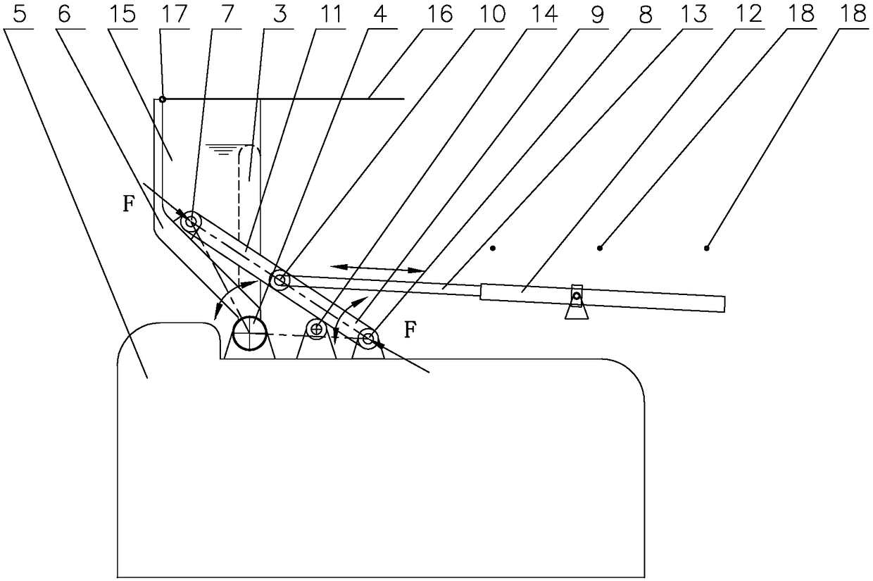
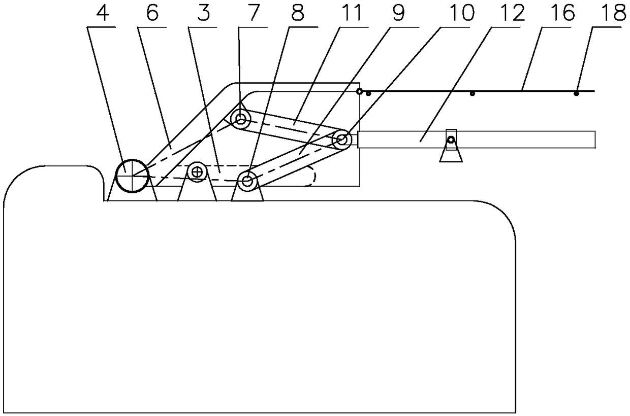
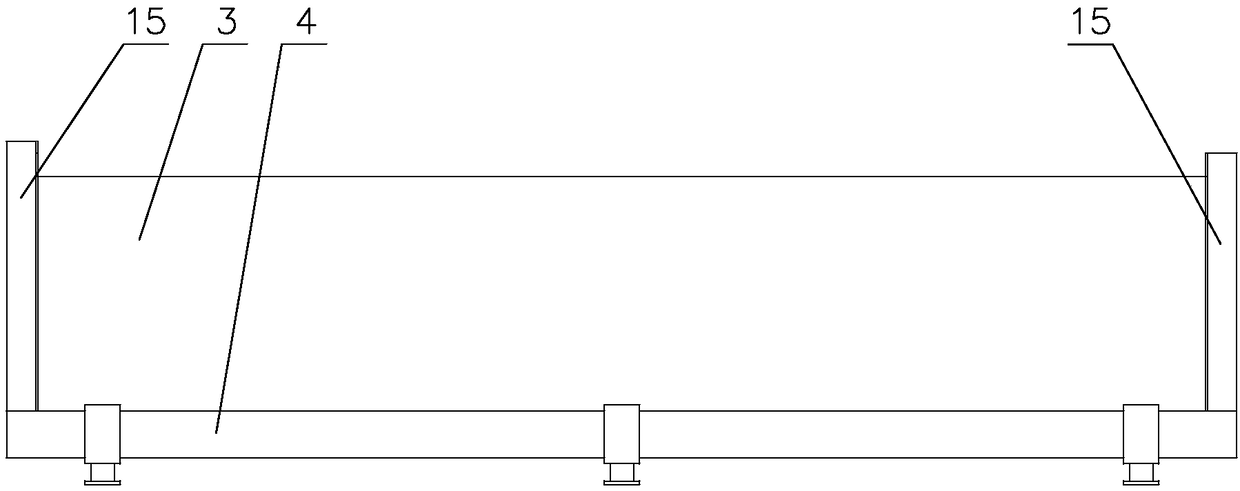
[0030] Figure 1 to Figure 5 It is a structural schematic diagram of a crank arm steel dam gate. As can be seen from the figure, it includes a steel dam door leaf 3 installed between the two left side walls 1 and right side wall 2, and the bottom of the steel dam door leaf 3 is connected with the dam body 5 through the bottom transverse shaft 4, and the steel dam The door leaf 3 swings around the bottom transverse axis 4 . When the steel dam door leaf 3 is swung up, the water can be blocked like figure 1 As shown, the hem achieves water release as figure 2 shown. The two ends of the steel dam door leaf 3 on the water-facing surface and the bottom transverse shaft 4 are welded with forward-extending curved arms 6 respectively, or the two ends of the steel dam door leaf 3 on the upstream-facing surface are respectively welded with forward-ex...


PUM


Abstract

The invention discloses a crank-arm steel dam gate comprising a steel dam gate leaf mounted between left and right side walls. The bottom of the steel dam gate leaf is connected with a dam body through a bottom cross shaft, and the steel dam gate leaf swings around the bottom cross shaft; water stopping is achieved when the steel dam gate leaf swings upwards, and water discharging is achieved whenthe steel dam gate leaf swings downwards. The crank-arm steel dam gate is characterized in that the steel dam gate leaf at the upstream face and / or the two ends of the bottom cross shaft are respectively connected with front extending crank arms, and a crank arm hinge is arranged on each crank arm; each crank arm hinge is connected with an opening and closing device which comprises a telescopic opening and closing oil cylinder, a water isolating plate is arranged on the steel dam gate leaf to isolate the crank arm exposed to the front of the upstream face from river water, the opening and closing devices are located at the rear end of the water isolating plate, and water sealing strips which are in contact with the left and right side walls are arranged on the water isolating plate. The crank-arm steel dam gate completely changes the basic shape and characteristics of a conventional steel dam gate, the defect which is not solved at present of the steel dam gate is overcome, and the crank-arm steel dam gate has important significance for popularization and application of the steel dam gate on water conservancy facilities.

Description

technical field [0001] The invention relates to a dam structure of a water conservancy facility, in particular to a crank arm steel dam gate. Background technique [0002] Steel dam gates are mechanical equipment in water conservancy and hydropower engineering facilities. It is mainly used in the construction of agricultural irrigation, fishery, ship locks, seawater tidal protection, urban river landscape engineering and small hydropower stations. The usual steel dam gate is a new type of gate that realizes the opening and closing of the steel dam gate by driving the bottom horizontal axis to rotate through hydraulic equipment. It has the advantages of rapid opening and closing, and durability. It mainly includes the bottom horizontal shaft, the steel dam door leaf, the hoist installed in the sluice chamber, etc. The steel dam door leaf is connected with the bottom horizontal shaft to form a gate, and the two ends of the bottom horizontal shaft pass through the walls of the...

Claims


Application Information

Patent Timeline
IPC IPC(8): E02B7/44
CPCE02B7/44
Inventor 郑建辉徐诗根
Owner 浙江河好闸门科技有限公司
Learn More