Water plant removing equipment operating in combination with unmanned ship and working method of water plant removing equipment

A technology of joint operations and working methods, applied in water conservancy projects, cleaning of open water surfaces, agriculture, etc., can solve problems such as damage to ships, damage to water ecological environment, infringement of water surface space, etc., and achieve the effect of easy installation and disassembly

Inactive Publication Date: 2018-06-15
苏州亮磊知识产权运营有限公司
View PDF2 Cites 4 Cited by
  • Summary
  • Abstract
  • Description
  • Claims
  • Application Information

AI Technical Summary

Problems solved by technology

[0002] On the water surface where ships sail, due to the existence of aquatic plants, it will cause great harm to ships, especially ships using power, and even damage ships and affect the service life of ships; , thereby encroaching on the space of the water surface, affecting the growth of other aquatic animals, and may also cause some aquatic plants to die and rot due to the vigorous growth of aquatic plants, polluting the environment, so it is very necessary to regularly remove aquatic plants
[0003] At present, most of the aquatic plants management only removes the aquatic plants on the water surface or the aquatic plants in the shallow water area, and ignores the aquatic plants in the depths of the water, which will destroy the ecological environment of the water area in the long run

Method used


Image

  • Water plant removing equipment operating in combination with unmanned ship and working method of water plant removing equipment
  • Water plant removing equipment operating in combination with unmanned ship and working method of water plant removing equipment
  • Water plant removing equipment operating in combination with unmanned ship and working method of water plant removing equipment

Examples


Embodiment 1

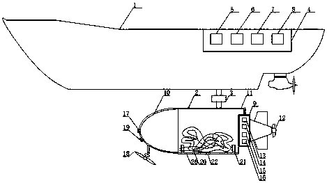
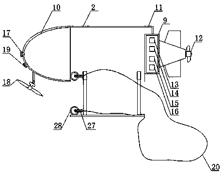
[0044] Such as figure 1 , 2As shown in , 3, a water weed removal equipment that works in conjunction with an unmanned ship includes an unmanned ship 1, a clearing device body 2, and a connection mechanism 3. The unmanned ship 1 includes a first control mechanism 4, and the first control mechanism 4 includes The first processor 5, the first driving device 6, the first navigation device 7 and the first positioning device 8, the first processor 5 is respectively connected with the first driving device 6, the first navigation device 7 and the first positioning device 8, The first navigation device 7 is used to generate the first navigation route of the unmanned ship 1, the first driving device 6 is used to drive the unmanned ship 1 to sail, and the first positioning device 8 is used to obtain the first position information of the unmanned ship 1, The cleaning device body 2 includes a second control mechanism 9, a cutting part 10, a storage part 11 and a screw propulsion mechanism...

Embodiment 2

[0054] Such as Figure 4 Shown, a kind of working method of the aquatic weed removal equipment of joint operation with the unmanned ship, comprises the following working steps:

[0055] a) The second processor 13 sets a preset water area in the second navigation device 15;

[0056] b) The second navigation device 15 automatically generates the travel route of the clearing device body 2 in the preset water area and sends the travel route to the second processor 13;

[0057] c) The second processor 13 outputs a travel signal to the second drive device 14, and the second drive device 14 drives the screw propulsion mechanism 12 to travel along the travel route;

[0058] d) The underwater camera 17 sends the shooting picture to the second processor 13 in real time;

[0059] e) the second processor 13 judges whether there are preset aquatic plants in the received picture;

[0060] f) if so, the second processor 13 extracts the location information of the roots of the preset aquat...

Embodiment 3

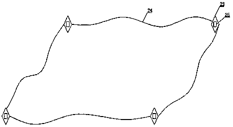
[0071] Such as Figure 7 As shown, step b also includes:

[0072] The navigation device generates the boundary route of the preset area and sends the boundary route to the first processor 5;

[0073] The first processor 5 outputs the second navigation signal to the first driving device 6, and the first driving device 6 drives the unmanned ship 1 to sail along the boundary route;

[0074] In the above process, the unmanned ship 1 arranges the warning mechanism on the boundary route, and the warning mechanism intercepts the water surface in the preset area.

[0075] Unmanned ship 1 arranges the warning mechanism on the border route and also includes:

[0076] When the unmanned ship 1 deploys the warning mechanism for the first time, the third positioning device 25 sends the third position information of the electronic buoy 23 to the first processor 5, and the first processor 5 records the third position information respectively;

[0077] The first processor 5 judges whether t...


PUM


Abstract

The invention discloses water plant removing equipment operating in combination with an unmanned ship and a working method of the water plant removing equipment. The water plant removing equipment operating in combination with the unmanned ship comprises the unmanned ship and a removing equipment body; the unmanned ship comprises a first control mechanism; the removing equipment body comprises a second control mechanism, a cutting portion, a storage portion and a screw propulsion mechanism; the second control mechanism comprises a second processor, a second drive device, a second navigation device and a second positioning device; the second navigation device is used for generating the traveling route of the removing equipment body; the second positioning device is used for obtaining secondposition information of the removing equipment body; the cutting portion comprises an underwater camera and a cutting device; the underwater camera is used for shooting the underwater environment; the cutting device is used for removing water plants; the storage portion comprises a containing net bag, an electric-hydraulic pusher and a movable chassis; the movable chassis is connected with the storage portion through the electric-hydraulic pusher; the screw propulsion mechanism is connected with the second drive device; and the screw propulsion mechanism is arranged at the tail end of a shelland used for controlling the underwater course of the removing equipment body.

Description

technical field [0001] The invention relates to the field of underwater operations, in particular to an aquatic weed removal device and a working method thereof for joint operation with an unmanned ship. Background technique [0002] On the water surface where ships sail, due to the existence of aquatic plants, it will cause great harm to ships, especially ships using power, and even damage ships and affect the service life of ships; , thereby encroaching on the space of the water surface, affecting the growth of other aquatic animals, and may also cause some aquatic plants to die and rot due to the vigorous growth of aquatic plants, polluting the environment, so it is very necessary to regularly remove aquatic plants. [0003] At present, most of the aquatic plants management only removes the aquatic plants on the water surface or the aquatic plants in the shallow water area, and ignores the aquatic plants deep in the bottom, which will destroy the ecological environment of...

Claims


Application Information

Patent Timeline
Patent Type & Authority Applications(China)
IPC IPC(8): E02B15/10A01D44/00
CPCE02B15/10A01D44/00
Inventor 吴静
Owner 苏州亮磊知识产权运营有限公司
Why Eureka
Try Eureka