
A hydraulic reciprocating drive mechanism and hydraulic reciprocating drive pump

A reciprocating drive and hydraulic technology, which is applied in the direction of machines/engines, liquid variable displacement machines, fluid pressure actuators, etc., can solve the problems of easy wear of moving parts, high maintenance costs, and large volume, and achieve simple drive control methods Effect

Active Publication Date: 2022-07-12
SHANGHAI MICROPOWERS
View PDF5 Cites 0 Cited by
  • Summary
  • Abstract
  • Description
  • Claims
  • Application Information

AI Technical Summary

Problems solved by technology

The three-cylinder single-acting reciprocating pump of this structure mostly adopts the motion principle of the crankshaft and connecting rod, and cannot be driven by hydraulic pressure, let alone automatically reversing. Its mechanical structure is complex, bulky, low in mechanical efficiency, and its moving parts are easy to wear and maintenance high cost

Method used


Image

  • A hydraulic reciprocating drive mechanism and hydraulic reciprocating drive pump
  • A hydraulic reciprocating drive mechanism and hydraulic reciprocating drive pump
  • A hydraulic reciprocating drive mechanism and hydraulic reciprocating drive pump

Examples


Embodiment Construction

[0039] In order to more clearly describe the embodiments of the present invention or the technical solutions in the prior art, the specific embodiments of the present invention will be described below with reference to the accompanying drawings. Obviously, the accompanying drawings in the following description are only some embodiments of the present invention. For those of ordinary skill in the art, other drawings can also be obtained from these drawings without creative efforts, and obtain other implementations. For the sake of brevity of the drawings, only the parts related to the present invention are schematically shown in the drawings, and they do not represent the actual structure as a product.

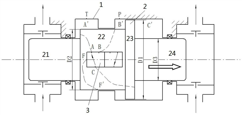
[0040] like image 3 and Figure 4 As shown in the figure, this specific embodiment discloses a hydraulic reciprocating drive mechanism, which includes a piston casing 1, a piston 2 and a hydraulic system (not shown in the figure). The hydraulic chamber is separated into a f...


PUM


Abstract

The invention discloses a hydraulic reciprocating driving mechanism and a hydraulic reciprocating driving pump. The hydraulic reciprocating driving mechanism comprises: a piston casing, a hydraulic chamber is arranged in the piston casing; a piston, the piston is arranged in the hydraulic chamber of the piston casing, and the hydraulic chamber is separated into The first hydraulic chamber, the second hydraulic chamber and the third hydraulic chamber; the hydraulic system, the hydraulic system feeds low-pressure liquid to the first hydraulic chamber, and feeds high-pressure liquid to the second hydraulic chamber, and the hydraulic system can be actuated to: Under a preset working condition, low-pressure liquid is introduced into the third hydraulic chamber, and the piston moves in the first direction; under the second preset working condition, high-pressure liquid is introduced into the third hydraulic chamber, the piston moves in the second direction, and the third hydraulic chamber moves in the second direction. The second direction is opposite to the first direction. The hydraulic reciprocating driving mechanism and the hydraulic reciprocating driving pump of the invention have compact structure, small volume, light weight, simple driving mode, automatic reversing, few wearing parts and low operating cost.

Description

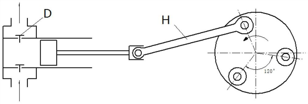
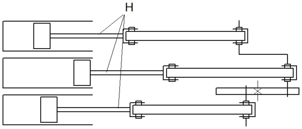
technical field [0001] The invention relates to the technical field of pump structure design, a hydraulic reciprocating drive mechanism and a hydraulic reciprocating drive pump. Background technique [0002] At present, in the application field of reciprocating pumps, the most widely used is the triplex single-acting piston reciprocating pump. figure 1 and figure 2 It is the working principle diagram of the widely used three-cylinder single-acting piston pump. exist figure 1 Driven by the right power source, the three pistons H of the reciprocating pump reciprocate left and right in different phases. The "T"-shaped element in the figure is the one-way valve D, and the one-way valve D will automatically open or close with the movement of the piston H. The three-cylinder single-acting reciprocating pump with this structure mostly adopts the movement principle of the crankshaft connecting rod, which cannot be driven by hydraulic pressure, nor can it be automatically revers...

Claims


Application Information

Patent Timeline
Patent Type & Authority Patents(China)
IPC IPC(8): F15B15/14F15B15/20F04B1/02F04B9/109
CPCF04B1/02F04B9/109F15B15/14F15B15/1447F15B15/202
Inventor 沈陆飞李天宇张锡杰黄嘉镔刘雁飞梁燕庄绪珍
Owner SHANGHAI MICROPOWERS
Learn More