Dynamic mutual inductance detecting method for mobile wireless power transmission system

A technology of wireless energy transmission and detection method, which is applied in the direction of inductance measurement, measurement device, and measurement of electrical variables, etc. It can solve problems that affect system efficiency and power transmission capability, high-frequency AC measurement error, and inaccurate mutual inductance detection, etc., to achieve Easy implementation, constant output voltage and high precision

Inactive Publication Date: 2018-06-15
XI AN JIAOTONG UNIV
View PDF5 Cites 11 Cited by
  • Summary
  • Abstract
  • Description
  • Claims
  • Application Information

AI Technical Summary

Problems solved by technology

[0003] In the mobile electric vehicle wireless power transmission system, when the electric vehicle moves, the mutual inductance value between the coupling coils will change due to their different shapes, different chassis heights, and different positions, which will affect the efficiency and power transmission capacity of the system. , so the system needs to adjust the control mode of the wireless power transfer system according to the change of the current mutual inductance value. However, the high-order nonlinearity of the system makes mutual inductance identification a problem
[0004] There are two main methods for existing mutual inductance detection methods: one is to use wireless communication technology, and the other is to identify methods based on reflection impedance. The phase difference between the high-frequency alternating currents, which is difficult to operate in the actual system, and the measurement error of the high-frequency alternating current will lead to inaccurate mutual inductance detection

Method used


Image

  • Dynamic mutual inductance detecting method for mobile wireless power transmission system
  • Dynamic mutual inductance detecting method for mobile wireless power transmission system
  • Dynamic mutual inductance detecting method for mobile wireless power transmission system

Examples


Embodiment

[0039] Set a set of basic parameters of the mobile wireless power transfer system as shown in Table 1.

[0040] Table 1

[0041]

[0042]

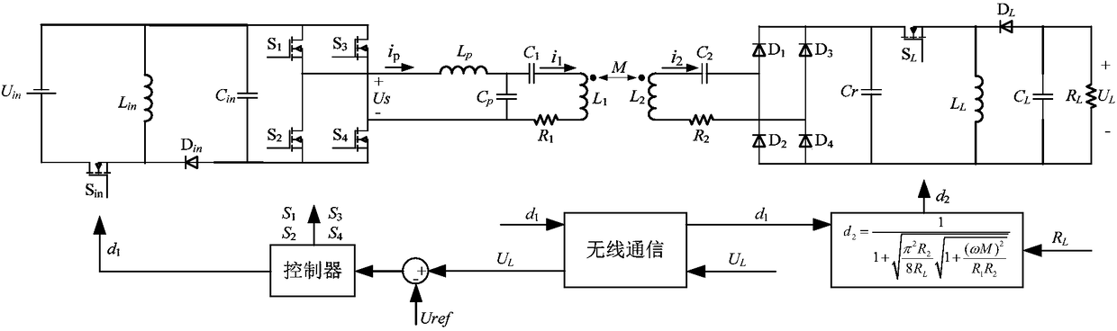
[0043] In the mobile wireless power transfer system, a control strategy with constant output voltage and optimal efficiency is adopted. There are two control variables under this control strategy: the duty cycle d of BUCK-BOOST on the input side 1 and the duty cycle d of BUCK-BOOST on the output side 2 , when M=15μH, R L =10Ω, U ref =45V, for the basic parameters in Table 1, it can be obtained that under this control strategy, the two control variables at steady state are: duty cycle d 1 is 0.346, d 2 is 0.5012.

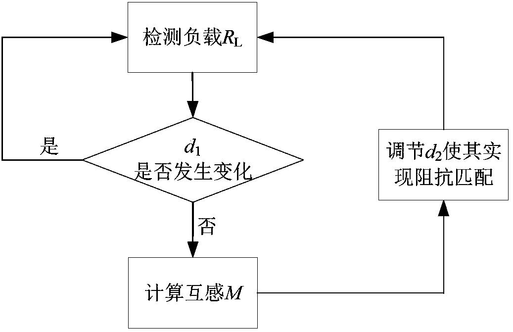
[0044] Suppose at this time due to the operation of the electric vehicle, the load R L And the mutual inductance M has changed, after the change M=25μH, R L =20Ω, U ref = 45V. Since the new mutual inductance value is unknown, impedance matching cannot be achieved, and system efficiency decreases. Mutual inductanc...


PUM


Abstract

The invention discloses a dynamic mutual inductance detecting method for a mobile wireless power transmission system. The method comprises the following steps: the mobile wireless power transmission system is built; the circuit of the system comprises a direct current power supply, a primary side voltage regulating circuit, a high frequency inverter circuit, a primary side compensation circuit, aprimary side wire coil, a secondary side wire coil, a secondary side compensation circuit, a rectifying and filtering circuit, a secondary side voltage regulating circuit and a load that are all connected in order; circuit parameters of mobile wireless power transmission system are determined; output voltage, the load, a duty ratio of the primary side voltage regulating circuit and a duty ratio ofthe secondary side voltage regulating circuit are detected; based on the circuit parameters obtained via detection in the above steps, a mutual inductance value is obtained via calculation. When themutual inductance changes during operation of an electric vehicle, change of the mutual inductance value M is detected via change of the duty ratio d1 of the primary side voltage regulating circuit, detection of high frequency alternating current quantities or even phase difference among the high frequency alternating current quantities in a resonant network of the wireless power transmission system is not needed. The method is high in detection accuracy and easy to implement.

Description

technical field [0001] The invention belongs to the technical field of wireless power transmission, and in particular relates to a dynamic mutual inductance detection method of a mobile wireless power transmission system. Background technique [0002] Traditional static electric vehicle wireless power transmission technology has disadvantages such as limited charging area, long charging time, short cruising range, and large battery size. In order to solve this problem, the mobile electric vehicle wireless power transmission technology has emerged as the times require, which can realize the charging of electric vehicles while driving, improve the battery life of electric vehicles, reduce the volume of the batteries on board, and even eliminate the need for batteries. [0003] In the mobile electric vehicle wireless power transmission system, when the electric vehicle moves, the mutual inductance value between the coupling coils will change due to their different shapes, diffe...

Claims


Application Information

Patent Timeline
Patent Type & Authority Applications(China)
IPC IPC(8): G01R27/26
CPCG01R27/2611
Inventor 王跃胡秀芳蒋勇斌雷万钧尹太元
Owner XI AN JIAOTONG UNIV
Why Eureka
Try Eureka