
A Distributed Voltage Control Method Based on Online Sensitivity

A voltage control method and sensitivity technology, which is applied in the direction of AC network voltage adjustment, circuit devices, AC network circuits, etc., can solve the problems of complex mutual coupling of voltage sensitivity and achieve the effect of simple online update

Active Publication Date: 2021-04-06
YUNNAN POWER GRID
View PDF6 Cites 0 Cited by
  • Summary
  • Abstract
  • Description
  • Claims
  • Application Information

AI Technical Summary

Problems solved by technology

Calculation of voltage sensitivity of unbalanced distribution feeders is very complicated due to mutual coupling between different phases and between unbalanced transformer banks

Method used


Image

  • A Distributed Voltage Control Method Based on Online Sensitivity
  • A Distributed Voltage Control Method Based on Online Sensitivity
  • A Distributed Voltage Control Method Based on Online Sensitivity

Examples


Embodiment 1

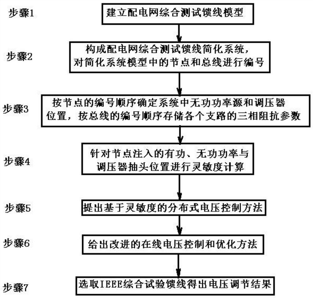
[0036] A distributed voltage control method based on online sensitivity, the process includes: solving the sensitivity matrix of the voltage amplitude of the controlled node relative to the injected reactive power and the tap change of the voltage regulator, adopting an iterative form according to the voltage change sensitivity matrix and injecting on the bus Simultaneously solve the voltage amplitude of the reactive power. Specific steps are as follows:

[0037] Step S1: Establish a distribution network comprehensive test feeder model, including:

[0038] The upper substation outlet bus bar of the distribution network is regarded as an infinite power source, as a balance node in the power flow calculation, the equivalent voltage amplitude and phase angle are constant known quantities and the three-phase voltage is assumed to be symmetrical; the All the loads on the branch are equivalent to the concentrated load at the end node of the branch; the branch adopts the centralized...

Embodiment 2

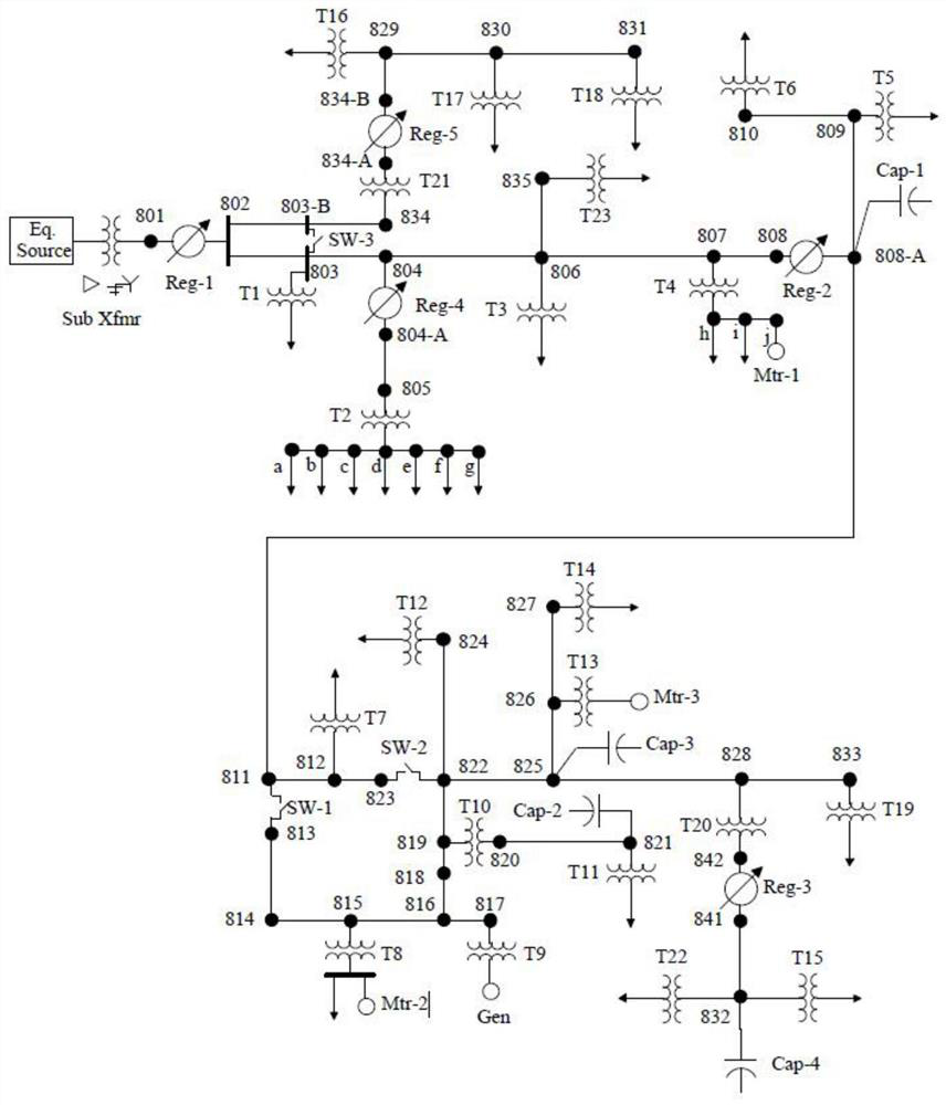
[0046] This embodiment is to provide the embodiment that the specific IEEE comprehensive test feeder carries out distributed voltage control, such as figure 2 Shown is the IEEE comprehensive test feeder model diagram provided by the present invention. As can be seen from the figure, there are 5 buses with SVRs: 701, 717, 735, 766 and 705. The first three are star connections, the fourth is a delta-delta connection, and the fifth is the opening Δ connection. Assuming that there is a reactive power source on phase a of the grounded bus 727, 760, 749, 713, there is also a reactive power source between phase a and phase b of the ungrounded bus 770, and the controlled voltage refers to the voltage between phase a and ground of the first four buses. voltage and the line voltage between phase a and phase b of the last busbar.

[0047] In the initial state, the reactive power injection from the reactive power source and the tap position of the voltage regulator is assumed to be zero, ...


PUM


Abstract

A distributed voltage control method based on online sensitivity, including first establishing a distribution network comprehensive test feeder model; then constructing a distribution network comprehensive test feeder simplified system, and numbering the nodes and buses in the simplified system model; The order of numbering determines the position of reactive power sources and voltage regulators in the system, stores the three-phase impedance parameters of each branch according to the numbering order of the bus; then performs sensitivity calculations for the active and reactive power injected into the nodes and the tap position of the voltage regulator; A distributed voltage control method based on sensitivity is proposed; an improved on-line voltage control and optimization method is given; finally, the IEEE comprehensive test feeder is selected to obtain the voltage regulation results. The invention completes the distributed voltage control by analyzing the on-line sensitivity, the calculation method is simple, and the on-line update of the sensitivity is simple.

Description

technical field [0001] The invention relates to the technical field of voltage control of power system distribution network, in particular to a distributed voltage control method based on online sensitivity. Background technique [0002] Voltage control is one of the main tasks of a distribution management system (DMS). Node voltages need to remain within allowable values ​​under various load conditions. This goal is achieved by using a step voltage regulator (SVR) and regulating the injected reactive power, mainly from controlled shunt capacitors and distributed generation such as photovoltaics (PV) and energy conversion systems (WECS) device provided. [0003] Coordination between reactive power sources and SVRs requires calculation of changes in voltage sensitivity after injecting reactive power and adjusting transformer taps. This coordination is crucial for the stability of the overall transient response and the optimization of steady-state reactive power injection. ...

Claims


Application Information

Patent Timeline
Patent Type & Authority Patents(China)
IPC IPC(8): H02J3/24H02J3/16H02J3/06
CPCH02J3/06H02J3/16H02J3/24H02J2203/20Y02E40/30
Inventor 路学刚王珍意叶华韩校赵川赵莹
Owner YUNNAN POWER GRID
Learn More