
Wind-energy long afterglow luminescence device

A technology of long afterglow luminescence and long afterglow luminous body, which is applied in wind power generation, display devices, wind turbines for storing electricity, etc. It can solve problems such as inability to use light emitting devices, inconvenient power supply, device damage, etc., and improve lighting safety Guarantee, reduce transmission loss and use cost, and reduce the effect of failure probability

Pending Publication Date: 2018-06-15
方显峰
View PDF3 Cites 4 Cited by
  • Summary
  • Abstract
  • Description
  • Claims
  • Application Information

AI Technical Summary

Problems solved by technology

[0003] However, most of the existing light-emitting devices with better effects use mains power supply or partially use mains power supply, which has the following disadvantages: 1. Since the light-emitting devices in some places above require long-term uninterrupted light emission, it not only causes a large amount of power consumption, but also It is easy to cause line failure or device damage; 2. Due to the need to lay lines to connect to the city power grid, the cost of installation and maintenance is relatively high; 3. Because some of the above places are inconvenient to pull electricity or because the pull distance is too long, the cost is high , or it needs to be isolated from the mains grid for separate power supply to ensure the secondary lighting function, so this kind of lighting device cannot be used
How to meet the demand for secondary lighting protection in such places when the conventional power supply lighting system fails, especially the rigid demand for uninterrupted lighting has become a problem that has plagued the industry for many years, and there has been no better way to solve it

Method used


Image

  • Wind-energy long afterglow luminescence device
  • Wind-energy long afterglow luminescence device
  • Wind-energy long afterglow luminescence device

Examples


Embodiment 1

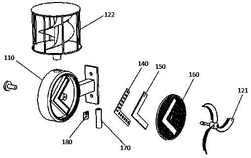
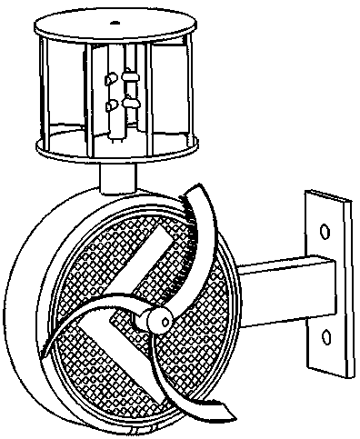
[0090] A wind energy long afterglow luminous guiding sign, comprising a casing (110), a wind mechanical structure (121) (122), a power generation device, an LED illuminant (140), a long afterglow illuminant (150), and a retroreflector (160) , storage element (170), control circuit (180), such as figure 2 , 3 shown.

[0091] Housing (110):

[0092] The housing (110) is a circular identification housing made of white ABS resin through an injection molding process. A circular surface of the casing (110) is a marking surface, and a circular opening with an arrow-shaped groove at the bottom is provided on the marking surface, and a protrusion with a hole in the center is provided at the center of the opening of the circular groove.

[0093] The right side of the logo housing (110) is provided with an aluminum alloy installation mechanism, which is fixed on the logo housing (110) by screws.

[0094] Wind Machinery Structure (121) (122):

[0095] The wind mechanical structure i...

Embodiment 2

[0113] A wind-solar complementary long-afterglow luminous guiding sign, including a casing, a wind mechanical structure, a power generation device, an LED luminous body, a long-lasting luminous body, a retroreflector, an electric storage element, a control circuit, and a photovoltaic module, such as Figure 4 shown.

[0114] case:

[0115] The shell is a round logo shell made of white ABS resin through injection molding process. A circular surface of the casing is a marking surface, and a circular opening with an arrow-shaped groove at the bottom is provided on the marking surface, and a protrusion with a hole in the center is provided at the center of the opening of the circular groove.

[0116] There is an aluminum alloy installation mechanism under the identification housing, which is fixed on the housing by screws.

[0117] Wind Machinery Structure:

[0118] The wind mechanical structure is a horizontal axis rotating mechanism (windmill mechanism), including a rotating ...

Embodiment 3

[0135] A wind energy long afterglow luminous escape sign, including a casing, a wind mechanical structure, a power generation device, an LED luminous body, and a long afterglow luminous body, such as Figure 5 shown.

[0136] case:

[0137] The shell is made of white ABS resin through injection molding process, and there are two logo planes intersecting at 150 degrees on the front. The surface of the logo surface is embedded with a square panel made by ABS resin injection molding process and hollowed out with an escape pattern.

[0138] The back of the logo housing is provided with an aluminum alloy installation mechanism, which is fixed on the logo housing by screws.

[0139] Wind Machinery Structure:

[0140] The wind mechanical structure is a Venturi-type wind mechanical structure, that is, a driving wind wheel is arranged in a Venturi tube, and the driving wind wheel is connected with the power generation device in the housing cavity. The Venturi-type wind mechanical s...


PUM


Abstract

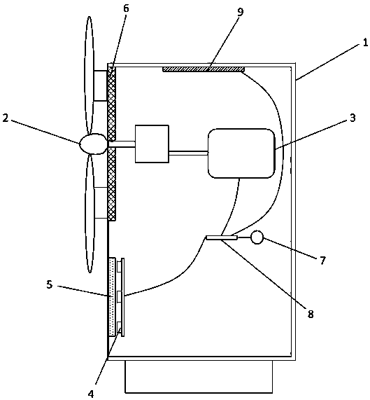
A wind-energy long afterglow luminescence device comprises a casing (1), a wind power mechanical structure (2), a power generation device (3), LED luminous bodies (4) and a long afterglow luminous body (5); the power generation device (3) is connected with the wind power mechanical structure (2) and the LED luminous bodies (4) via lines respectively; and the wind power mechanical structure (2), driven by wind power, enables that the power generation device (3) drives the LED luminous bodies (4) to emit light and excites the long afterglow luminous body (5) to emit light. Power is used once being generated, the power transmission loss and using cost are reduced, the problem that a common wind energy luminescence device is hard to emit light continuously with minimal brightness without routine power supply or under a power off condition is solved, uninterrupted light emission is realized, and the minimal brightens of afterglow luminescence is improved greatly compared with a traditionallong afterglow luminescence; and a speed change mechanism can be used to improve the wind power generation efficiency further, a photovoltaic device can be combined, and wind and photovoltaic hybrid power supply is used to improve the safety of light emission.

Description

technical field [0001] The invention relates to the field of light emitting devices, in particular to a wind energy long afterglow light emitting device. Background technique [0002] In recent years, with the rapid development of society and economy, especially the progress of construction technology, the number of various underground buildings and underground transportation facilities such as: underground shopping malls, highway tunnels, subway tunnels, bridge culverts, etc. getting bigger. These places, especially some of the large-scale underground projects such as the Hong Kong-Zhuhai-Macao Bridge subsea tunnel, etc., are facing more and more needs for emergency lighting, security instructions and low-light lighting; and in such as: underground mines, underground air defense facilities Special lighting, emergency lighting, and escape indicating devices are also required in specific places such as weapons and ammunition depots to meet the rigid requirements of uninterru...

Claims


Application Information

Patent Timeline
IPC IPC(8): H02S40/22H02S10/12H02S40/38F03D9/11G09F13/20G09F13/22
CPCH02S10/12H02S40/22H02S40/38G09F13/20G09F13/22F03D9/11G09F2013/222Y02E10/52Y02E10/72Y02P70/50Y02E70/30
Inventor 方显峰
Owner 方显峰
Learn More