Glue joint structure of motor surface mounting magnetic steel and rotor and glue joint method thereof

A surface-mounted, magnetic steel technology, applied in the magnetic circuit shape/style/structure, manufacturing of motor generators, magnetic circuit rotating parts, etc., can solve the problem of inconsistent size of electromagnetic air gap between stator and rotor, surface-mounted magnetic steel separation Rotor, parameter instability and other problems, to achieve the effect of improving production efficiency, improving sticking effect, and simple processing

Active Publication Date: 2018-06-19
NANJING ESTUN AUTOMATION CO LTD
View PDF9 Cites 2 Cited by
  • Summary
  • Abstract
  • Description
  • Claims
  • Application Information

AI Technical Summary

Problems solved by technology

At present, many motor manufacturers do not design and control the thickness of the adhesive layer and the structure of the adhesive. They just apply glue on the surface of the magnet and the rotor and then directly install the magnet. When the thickness of the glue does not meet the requirements, such as too thick or If the thickness is too thin, or the effective sticking area is smaller than the sticking requirement, it will directly lead to the inconsistency of the electromagnetic air gap size between the stator and the rotor, and the motor output, back EMF and other parameters are unstable or out of tolerance. Stress cracking causes the surface-mounted magnetic steel to detach from the rotor, causing motor accidents

Method used


Image

  • Glue joint structure of motor surface mounting magnetic steel and rotor and glue joint method thereof
  • Glue joint structure of motor surface mounting magnetic steel and rotor and glue joint method thereof
  • Glue joint structure of motor surface mounting magnetic steel and rotor and glue joint method thereof

Examples


Embodiment Construction

[0029] The invention proposes a small-scale structure change on the motor rotor, so as to obtain a stable adhesive layer and a consistent rotor diameter required for pasting magnetic steel. This solution has compact and simple structure, strong controllability, stable and reliable glue layer, greatly saves the amount of glue used for pasting, and improves the production efficiency of pasting magnetic steel.

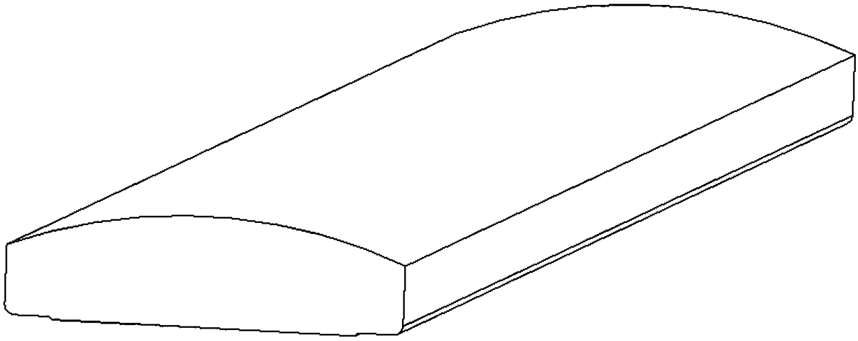
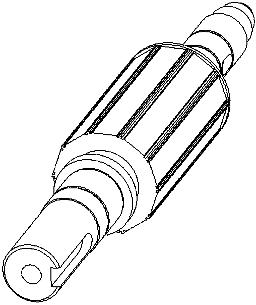
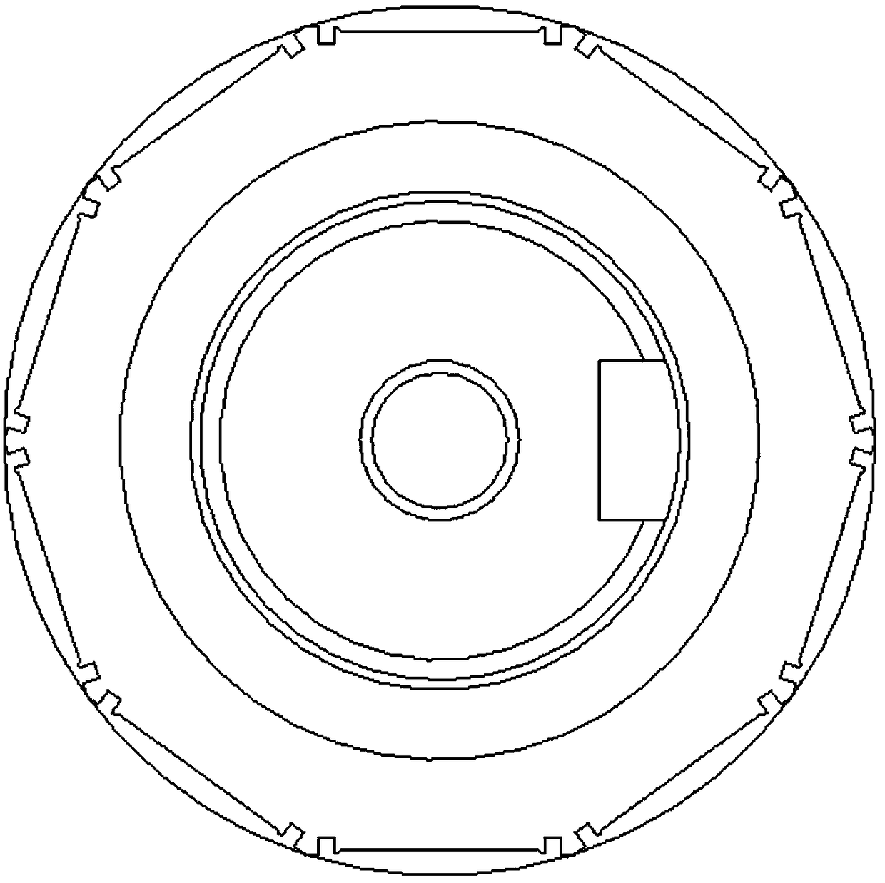
[0030] Figure 1-4 An embodiment of the structure of the surface-mounted magnetic steel and the rotor shaft of the present invention is shown. The surface of the rotor shaft is provided with a glue groove structure for installing the surface-mounted magnetic steel. The glue groove structure is evenly arranged around the rotor shaft. The implementation of the present invention will be described in detail below in conjunction with the accompanying drawings and examples.

[0031] like Figure 5-9 As shown, the surface-mounted magnets are pasted on the surface of the shaft ...


PUM


Abstract

The present invention relates to a glue joint structure of a motor surface mounting magnetic steel and a rotor and a glue joint method thereof. The surface mounting magnetic steel is adhered on a shaft surface of the rotor, the shaft surface is equipped with a glue groove structure corresponding to the surface mounting magnetic steel, and the glue groove structure comprises a main glue groove andtwo glue shunting storage grooves. After the glue is filled in the main glue groove, the magnetic steel is positioned to the corresponding position of the glue groove structure, and a protruding partof the magnetic steel is sunk in the main glue groove. By the mutual cooperation of the glue groove structures of the magnetic steel and the rotor shaft, the redundant glue in the main glue groove isextruded to the glue shunting storage grooves, a stable glue layer of which the thickness is b is formed between the main glue groove and the magnetic steel, and according to the glue curing demands,the glue is cured, thereby finishing the glue joint of the magnetic steel and the rotor. The glue joint structure scheme of the present invention is convenient and simple to operate during the whole process, enables the stability and the reliability of the glue layer to be improved, the glue usage amount to be saved greatly and the production operation efficiency to be improved, effectively controls the diameter size of the rotor, and guarantees the consistency of the electromagnetic sizes.

Description

technical field [0001] The invention belongs to the technical field of motors, relates to the connection between a surface-mounted magnetic steel and a rotor, and relates to a bonding structure and a bonding method for a surface-mounted magnetic steel and a rotor of a motor. Background technique [0002] In the existing motor industry, whether it is a motor or a servo motor, there are applications of surface-mounted magnets; the control of the installation and assembly dimensions of the surface-mounted magnets will directly affect the electromagnetic air gap between the stator and rotor of the motor, thereby Affects the final operating parameters of the motor. The main impact is that when the surface-mounted magnetic steel is attached to the surface of the rotor, both the installation size and the installation effect will be affected by the thickness of the adhesive layer. At present, many motor manufacturers do not design and control the thickness of the adhesive layer and...

Claims


Application Information

Patent Timeline
Patent Type & Authority Applications(China)
IPC IPC(8): H02K1/27H02K15/03
CPCH02K1/27H02K15/03H02K2213/03
Inventor 刘冬周楠钱巍徐正华吴波
Owner NANJING ESTUN AUTOMATION CO LTD
Why Eureka
Try Eureka