
Automobile injection mold

A technology for injection molds and automobiles, which is applied in the field of mold processing, can solve the problems of long heat dissipation time of plastic melt, and achieve the effects of reducing molding costs, high efficiency, and reducing costs

Active Publication Date: 2018-06-22
CHONGQING YINSHENG MOLD
View PDF6 Cites 11 Cited by
  • Summary
  • Abstract
  • Description
  • Claims
  • Application Information

AI Technical Summary

Problems solved by technology

[0005] The purpose of the present invention is to provide an automobile injection mold to solve the problem that the heat dissipation time of the plastic melt in the injection mold is long

Method used


Image

  • Automobile injection mold
  • Automobile injection mold
  • Automobile injection mold

Examples


Embodiment 1

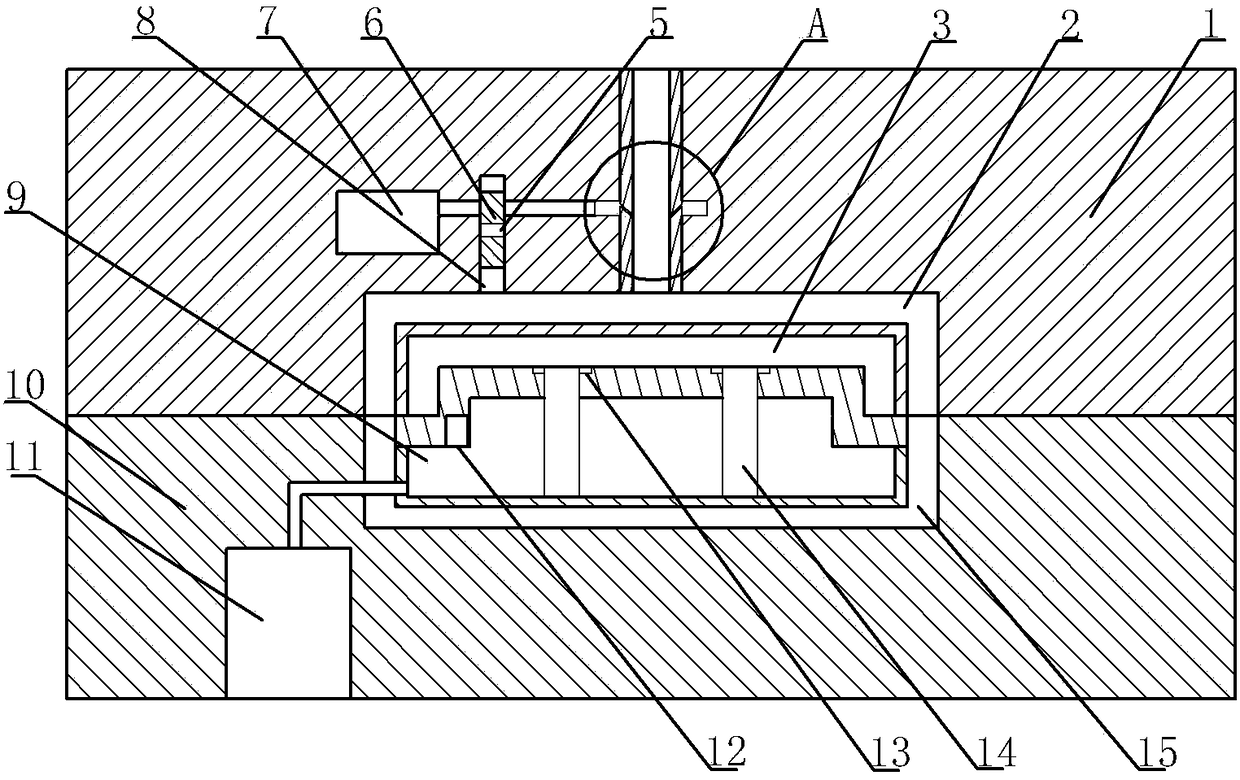
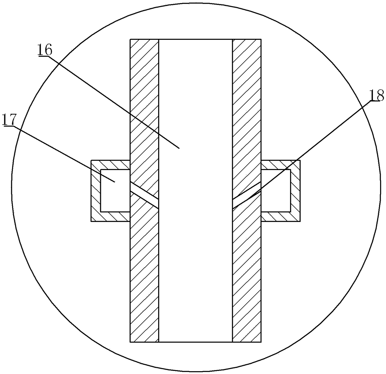
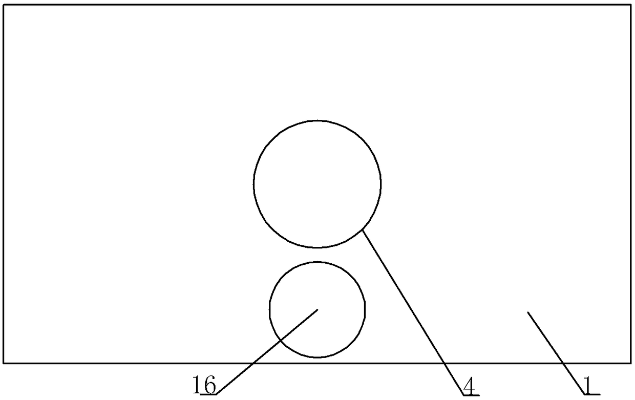
[0024] as attached figure 1 , attached figure 2 And attached image 3 As shown, a kind of automobile injection mold comprises the upper die of die 1 and the lower die of punch 10. When the punch 10 and die 1 are engaged, a closed molding cavity 3 is formed between the upper die and the lower die. . The die 1 is provided with an injection channel 4 and an air channel 16 , and the air channel 16 is parallel to the injection channel 4 . An annular cavity 17 is provided on the outer periphery of the air channel 16 , and an air outlet 18 communicating with the annular cavity 17 is provided on the air channel 16 . One side of the air passage 16 is provided with a high-pressure air cavity 7 that can communicate with the annular cavity 17 . A slide groove is provided between the high-pressure air cavity 7 and the air passage 16, and a slide block 6 slidably connected with the die 1 is arranged in the slide groove, and the slide block 6 can slide vertically on the die 1. A connec...

Embodiment 2

[0033] On the basis of Embodiment 1, a refrigerator is installed on the upper mold, and the air outlet 18 of the refrigerator is communicated with the air channel 16. When the air channel 16 is under the action of high-pressure gas, the cold air generated by the refrigerator will be sucked , and enter the upper cooling channel 2 and the lower cooling channel 15, thereby accelerating the rapid cooling of the plastic melt in the molding cavity 3.


PUM


Abstract

The invention relates to the technical field of mold machining, and discloses an automobile injection mold. The automobile injection mold comprises an upper mold and a lower mold. The upper mold is aconcave mold, and the lower mold is a convex mold. When the upper mold and the lower mold are clamped, a closed molding cavity is formed between the upper mold and the lower mold. An injection moldingchannel and a gas channel are arranged on the concave mold. An annular cavity is formed in the periphery of the gas channel. A gas outlet communicating with the annular cavity is formed in the gas channel. The gas outlet inclines downwards and faces the interior of the gas channel. A high-pressure gas cavity communicating with the annular cavity is formed in one side of the gas channel. A slidingblock is arranged between the high-pressure gas cavity and the gas channel and provided with a connector. A gas bag is arranged below the sliding block. An upper cooling channel communicates with thegas channel. The convex part of the convex mold comprises a balance cavity and a sliding plate. The sliding plate is in sliding connection with the convex mold and closes the balance cavity. A pressure reduction valve is fixed to the sliding plate. A limiting block is arranged on the sliding plate. A high-pressure gas pump and a lower cooling channel are arranged in the convex mold. The high-pressure gas pump communicates with the balance cavity. According to the automobile injection mold, plastic melt in the molding cavity can be fast cooled, and the mold molding efficiency can be improved.

Description

technical field [0001] The invention relates to the technical field of mold processing, in particular to an automobile injection mold. Background technique [0002] Injection molding is a method of producing shapes for industrial products. Products are usually injection molded with rubber or plastic. Injection molding can also be divided into injection molding molding method and die casting method. [0003] The vast majority of auto parts are molded by injection molding. Generally, injection molding machines, namely injection machines and injection molding machines, are used. Injection molding machines make thermoplastic or thermosetting plastics into various shapes of plastic auto parts using plastic molding molds. , so the injection molding of auto parts is achieved through injection molding machines and injection molds. [0004] The existing injection mold includes a die and a lower die. The die is a die and the die is a punch. When the die and the die are engaged, a c...

Claims


Application Information

Patent Timeline
IPC IPC(8): B29C45/26B29C45/73
CPCB29C45/26B29C45/2602B29C45/7312
Inventor 邱建华
Owner CHONGQING YINSHENG MOLD
Learn More