
Eureka
For R&D, Eureka makes reading and utilizing patents & technical documents easy.
Eureka AIR
Designed for self-driven R&D workflows. Generate viable solutions, solve complex R&D challenges, empower your innovation with AI.

Eureka Materials
Designed for material experts only. Revolutionize your material R&D, from search, analyze, to developing new materials.

TechResearch
Generate reliable direction feasibility study reports for your R&D in just a few steps.

TechSeek
Discover and master advanced knowledge NOW. Basics, ideas, possibilities, all at once.

TechMind
As an expert in R&D Theories, TechMind can generates customized viable solutions instantly.

TechRisk
Analyze your overall solution with one click, know your potential R&D risks in advance.

TechMonitor
Get weekly tech updates, stay abreast of the latest tech innovations and key insights.
Cement conveying system for nuclear power plant
A technology for conveying systems and nuclear power plants, applied in the directions of conveyors, transportation and packaging, loading/unloading, etc., can solve the problems of only one-way conveying, blockage and drying, loss and pollution, etc., so as to improve the conveying efficiency and prevent drying and blockage, the effect of increasing the degree of automation
- Summary
- Abstract
- Description
- Claims
- Application Information
AI Technical Summary
Problems solved by technology
Method used
Image

Examples
Embodiment 1
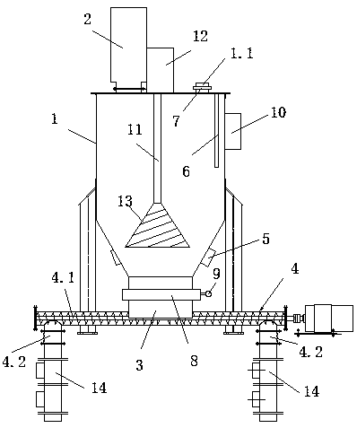
[0009] Embodiment 1: A nuclear power plant cement delivery system, including a cement silo 1, a bag filter 2 arranged on the top of the cement silo 1 and connected to it, and the discharge port at the bottom of the cement silo 1 is connected through a discharge pipe 3 The feeding port of the screw conveyor 4, the screw conveyor 4 is provided with two discharge ports 4.2 respectively located on both sides of the feeding port of the screw conveyor 4, and the side wall near the bottom of the cement silo 1 is provided with a bin wall vibrator 5. A level meter 6 is arranged in the cement silo 1, and a No. 1 solenoid valve 7 is arranged at the feed inlet 1.1 at the top of the cement silo 1 . The discharge pipeline 3 is provided with a No. 2 solenoid valve 8, and the No. 2 solenoid valve 8 is provided with a pressure gauge 9. The cement silo 1 is provided with a PLC controller 10, and the PLC controller 10 is signal-connected to the level meter 6, the pressure meter 9, and No. 1 and...
Embodiment 2
[0010] Embodiment 2: Referring to Embodiment 1, the cement silo 1 is provided with a stirring shaft 11 , the top end of the stirring shaft 11 is connected to a motor 12 , and the bottom end of the stirring shaft 11 is provided with a helical elastic coil 13 .
[0011] Workflow: The cement conveying system conveys dry cement to the grouting receiving silo or the curing receiving silo. When the level meter reaches a high setting value, close the inlet valve, and when it reaches a low setting value, close the outlet valve; when the pressure meter reaches high pressure, close the inlet valve, and when the pressure is low, close the outlet valve. When the conveying pipe is blocked, the bin wall vibrator is turned on to loosen the densely packed cement and prevent the cement from agglomerating. The screw conveyor can rotate forward and reverse to transport cement to the two silos respectively.
PUM
 Abstract
Description
Claims
Application Information
 - R&D Engineer
- R&D Manager
- IP Professional
- Industry Leading Data Capabilities
- Powerful AI technology
- Patent DNA Extraction
Browse by: Latest US Patents, China's latest patents, Technical Efficacy Thesaurus, Application Domain, Technology Topic, Popular Technical Reports.
© 2024 PatSnap. All rights reserved.Legal|Privacy policy|Modern Slavery Act Transparency Statement|Sitemap|About US| Contact US: help@patsnap.com