
Centrifugal slag granulation and waste heat recovery system

A waste heat recovery system and centrifugal technology, applied in recycling technology, furnaces, waste heat treatment, etc., can solve the problems of wasting heat energy resources, not making full use of high-temperature slag heat, and wasting water resources, so as to save water resources and increase heat Recovery efficiency, anti-blocking effect

Inactive Publication Date: 2018-06-22
秦皇岛点知汇科技有限公司 +1
View PDF8 Cites 10 Cited by
  • Summary
  • Abstract
  • Description
  • Claims
  • Application Information

AI Technical Summary

Problems solved by technology

[0002] The iron and steel metallurgical industry will produce a large amount of high-temperature slag during the production process, but the above-mentioned secondary industrial products have not been fully and rationally utilized in the current production process. The usual treatment method is mainly "wet" treatment, that is, using water cooling Cooling and granulating the high temperature slag directly, this treatment process does not make full use of the heat of the high temperature slag itself, but this part of the heat energy is considerable, that is, a lot of heat energy resources are wasted, and the "wet" treatment needs to use a lot of energy. Water resources have caused a waste of water resources. In the context of energy conservation and emission reduction, the existing production process obviously needs to be better optimized and upgraded

Method used


Image

  • Centrifugal slag granulation and waste heat recovery system
  • Centrifugal slag granulation and waste heat recovery system
  • Centrifugal slag granulation and waste heat recovery system

Examples


Embodiment

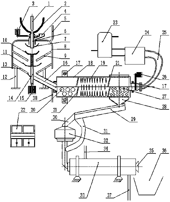
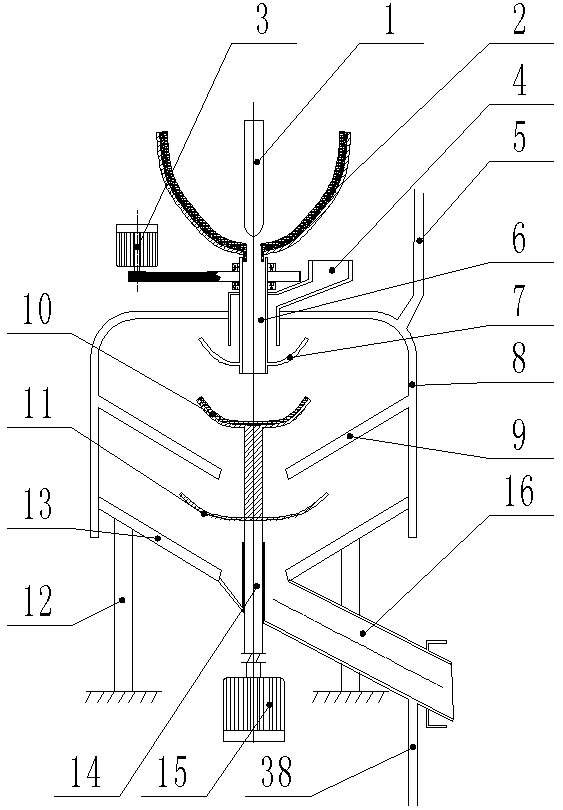
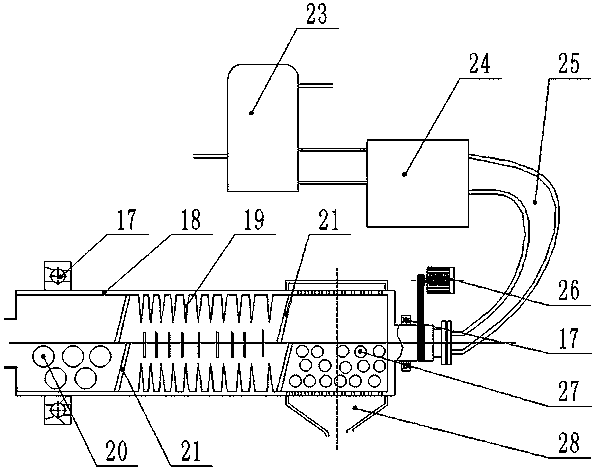
[0027] Embodiment: the structure of the present invention is as Figure 1 to Figure 4 As shown, in the specific working process, the heat recovery structure in the agglomeration part and the granulation part in the present invention is an integral low-temperature heat recovery system, which is specifically realized by the following structure: the tank body wall of the slag agglomeration tank 8 is provided with water Cooling layer, the transition channel 16 is also provided with a water cooling layer, and communicates with the water cooling layer of the slag agglomerating tank 8, the upper part of the slag agglomerating tank 8 is provided with a cooling water outlet 5, and the cooling water outlet 5 is connected to the slag agglomerating tank The water cooling layer of the tank 8 is connected, and the lower part of the transition channel 16 is provided with a cooling water inlet 38 , and the cooling water inlet 38 is in communication with the water cooling layer of the transitio...


PUM


Abstract

The invention discloses a centrifugal slag granulation and waste heat recovery system. A 'dry-type' treatment method is adopted for slag, and a large quantity of water resources can be saved. According to the centrifugal slag granulation and waste heat recovery system, high-temperature slag is subjected to segmented heat recovery, and the first segment is primarily cooled in a water-cooled wall mode at first; and meanwhile the high-temperature slag is subjected to slag throwing treatment with a slag throwing structure, cold slag and hot slag can be mixed in the slag throwing process, adhesionof the hot slag is prevented and meanwhile agglomeration can be facilitated. By means of the centrifugal slag granulation and waste heat recovery system, after the high-temperature slag is subjected to the first segment of slag throwing agglomeration and heat recovery, the second segment of ball-milling tank heat recovery and crushing procedure is conducted; and meanwhile the absorbed heat is conveyed to a steam boiler and used for generating steam. By adoption of the centrifugal slag granulation and waste heat recovery system, the heat recovery efficiency of the slag is improved, and the pelletization effect of the slag is effectively improved. The first segment of heat recovery and the third segment of heat recovery are series-connection low-temperature heat recovery, and the heat recovery efficiency is effectively improved through segmented recovery of the heat.

Description

technical field [0001] The invention relates to a slag treatment system, in particular to a centrifugal slag granulation and waste heat recovery system. Background technique [0002] The iron and steel metallurgical industry will produce a large amount of high-temperature slag during the production process, but the above-mentioned secondary industrial products have not been fully and rationally utilized in the current production process. The usual treatment method is mainly "wet" treatment, that is, using water cooling Cooling and granulating the high temperature slag directly, this treatment process does not make full use of the heat of the high temperature slag itself, but this part of the heat energy is considerable, that is, a lot of heat energy resources are wasted, and the "wet" treatment needs to use a lot of energy. Water resources have also caused a waste of water resources. In the context of energy conservation and emission reduction, the existing production proces...

Claims


Application Information

Patent Timeline
IPC IPC(8): C21B3/06C21B3/08F27D17/00
CPCC21B3/06C21B3/08F27D17/004Y02P10/20Y02P10/25Y02W30/50
Inventor 刘凡邢鹏达冯圣冰吕庆东刘阳彭艳
Owner 秦皇岛点知汇科技有限公司
Learn More