Air heating furnace cooling water supply system and control method

A technology of water supply system and control method, which is applied in the field of iron and steel metallurgy, and can solve the problems that the cooling water of the hot blast stove cannot be operated independently, and the independent water supply of cooling equipment cannot be realized, so as to save time and increase the utilization rate

Active Publication Date: 2018-06-22
ANHUI MA STEEL EQUIP MAINTENANCE CO LTD
View PDF5 Cites 5 Cited by
  • Summary
  • Abstract
  • Description
  • Claims
  • Application Information

AI Technical Summary

Problems solved by technology

But its disadvantage is that the closed circulation system of blast furnace soft water is connected with the soft water of the hot blast valve and shutdown valve of the hot blast stove, so the valves of the hot blast stove cannot realize the independent water supply of the cooling equipment
But its shortcoming is that the cooling water of the hot blast stove valve is connected with the soft water of the blast furnace, and the cooling water of the hot blast stove cannot be operated independently.

Method used


Image

  • Air heating furnace cooling water supply system and control method

Examples


Embodiment 1

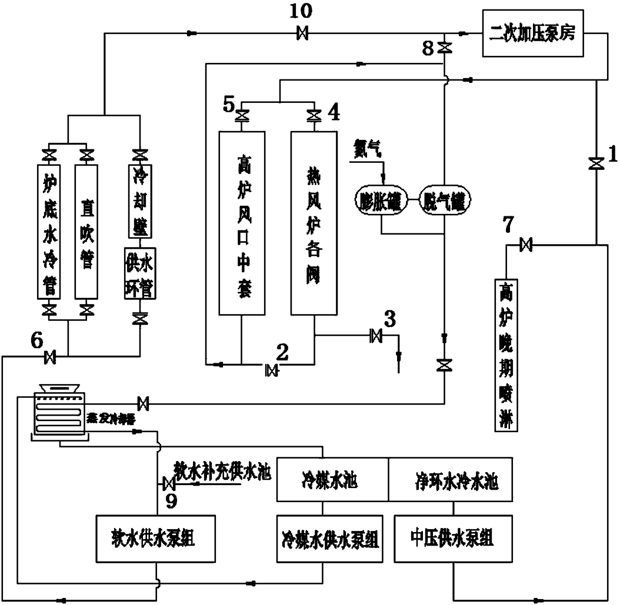
[0033] Such as figure 1 As shown, the hot blast stove cooling water supply system of this embodiment includes several hot blast stove valves, medium pressure water supply pump sets and a secondary pressurization pump room, and is characterized in that: the soft water pipeline output by the secondary pressurization pump room is set The switch valve I1 and the connecting pipe connect the soft water pipe output from the secondary pressurization pump room with the medium pressure water pipe output from the medium pressure water supply pump unit; the connected soft water pipe branches into the valves of the hot blast stove and the middle sleeve of the blast furnace tuyere. The on-off valve IV4 is set at the water inlet pipe of each valve of the hot blast stove, and the on-off valve V5 is set at the water inlet pipe in the tuyere of the blast furnace; a three-way pipe is set on the soft water pipe output from each valve of the hot blast stove, and the three-way pipe includes the inle...

Embodiment 2

[0037] Such as figure 1 As shown, this embodiment is basically the same as Embodiment 1. Preferably, the soft water pipeline containing the on-off valve II2 is connected in parallel with the outlet water pipe in the tuyere of the blast furnace and then connected in series, and then divided into two paths, one path enters the evaporative cooler through the degassing tank , the switch valve Ⅷ8 is set on the other soft water pipeline, and then input to the secondary pressurization pump room; the degassing tank is connected with the expansion tank, and nitrogen gas is introduced into the expansion tank, and the degassing tank and the evaporative cooler At least one switch valve is arranged on the soft water pipeline.

[0038] In this embodiment, the switching valve II is a DN250 valve.

[0039] In this embodiment, nitrogen gas is charged into the expansion tank to detect whether the soft water pipeline is filled with soft water; the switch valve provided on the return water pipel...

Embodiment 3

[0041] Such as figure 1 As shown, this embodiment is basically the same as Embodiment 2. Preferably, the soft water pipeline output by the evaporative cooler is connected to the soft water supply pump set, and the soft water pipeline between the evaporative cooler and the soft water supply pump set is supplemented with soft water The pipeline is connected, and the soft water supply pipeline is connected with the soft water supply pool; the switch valve Ⅸ9 is set on the soft water supply pipeline; the branch pipe of the evaporative cooler is connected with the refrigerant pool, and the refrigerant water pool is connected with a refrigerant water supply pump group, and a refrigerant water supply pump group The water in the refrigerant pool is supplied to the evaporative cooler.

[0042] In this embodiment, the soft water replenishment water supply pool provides soft water for the blast furnace, and the refrigerant pool is used for cooling by the evaporative cooler.


PUM


Abstract

The invention discloses an air heating furnace cooling water supply system and a control method, and belongs to the field of ferrous metallurgy. The air heating furnace cooling water supply system comprises multiple air heating furnace valves, an intermediate pressure water supply pump set and a secondary booster pump chamber. A switching valve I and a connecting pipe are arranged on a soft waterpipeline output from the secondary booster pump chamber. Communicated soft water pipeline branches enter the air heating furnace valves and a blast-furnace tuyere medium sleeve. A three-way pipe is arranged on soft water pipelines output from the air heating furnace valves, soft water sequentially flows through a water inlet pipe and a water outlet pipe of the three-way pipe, a branch pipe is connected with a drainage pipe of the three-way pipe, and a switching valve III is arranged on the drainage pipe. A switching valve II is arranged on the soft water pipeline connected with the water outlet pipe. According to the air heating furnace cooling water supply system and the control method, the air heating furnace valves and cooling water of blast furnace equipment can be connected together and can operate independently, it is guaranteed that a blast furnace can carry out cooling wall piping when the air heating furnace valves are cooled, washing water can be fast provided during blast furnace cooling wall washing, and even cooling of the air heating furnace valves is not influenced during blast furnace staying maintenance.

Description

technical field [0001] The invention relates to the field of iron and steel metallurgy, and more specifically relates to a hot blast stove cooling water supply system and a control method. Background technique [0002] At present, the cooling water of domestic hot blast stove valves is connected with the blast furnace soft water system. For the air valve water supply, the medium pressure water is the spray water in the late stage of the blast furnace, which is rarely used at ordinary times, and a small amount of soft water consumption in the circulation process is supplied by the soft water replenishment pump. The hot blast stove is earlier than the blast furnace oven. When the hot blast stove is baked, the hot blast valve and the shutoff valve also need to be cooled by water supply. Since the soft water of the hot blast valve and the shutoff valve is connected with the soft water of the blast furnace, this requires the entire soft water system The hot blast stove can only ...

Claims


Application Information

Patent Timeline
Patent Type & Authority Applications(China)
IPC IPC(8): C21B9/10C21B7/10
CPCC21B7/10C21B9/10
Inventor 章锐晋杰
Owner ANHUI MA STEEL EQUIP MAINTENANCE CO LTD
Why Eureka
Try Eureka