Spray welding wire drawing machine reel with high wear resistance

A wire drawing machine reel, high wear resistance technology, applied in the field of steel wire manufacturing, can solve the problems of easy scaling and muddying of the reel, reducing the heat exchange efficiency of the reel, etc., to ensure the heat exchange efficiency, easy to clean, prolong The effect of the service life

Active Publication Date: 2019-09-17
遵义市润丰源钢铁铸造有限公司
View PDF6 Cites 0 Cited by
  • Summary
  • Abstract
  • Description
  • Claims
  • Application Information

AI Technical Summary

Problems solved by technology

[0006] The purpose of the present invention is to provide a reel for spray welding wire drawing machine with high wear resistance, which solves the problem in the prior art that the inner wall of the reel is prone to fouling and mud, which reduces the heat exchange efficiency of the reel

Method used


Image

  • Spray welding wire drawing machine reel with high wear resistance
  • Spray welding wire drawing machine reel with high wear resistance

Examples


Embodiment 1

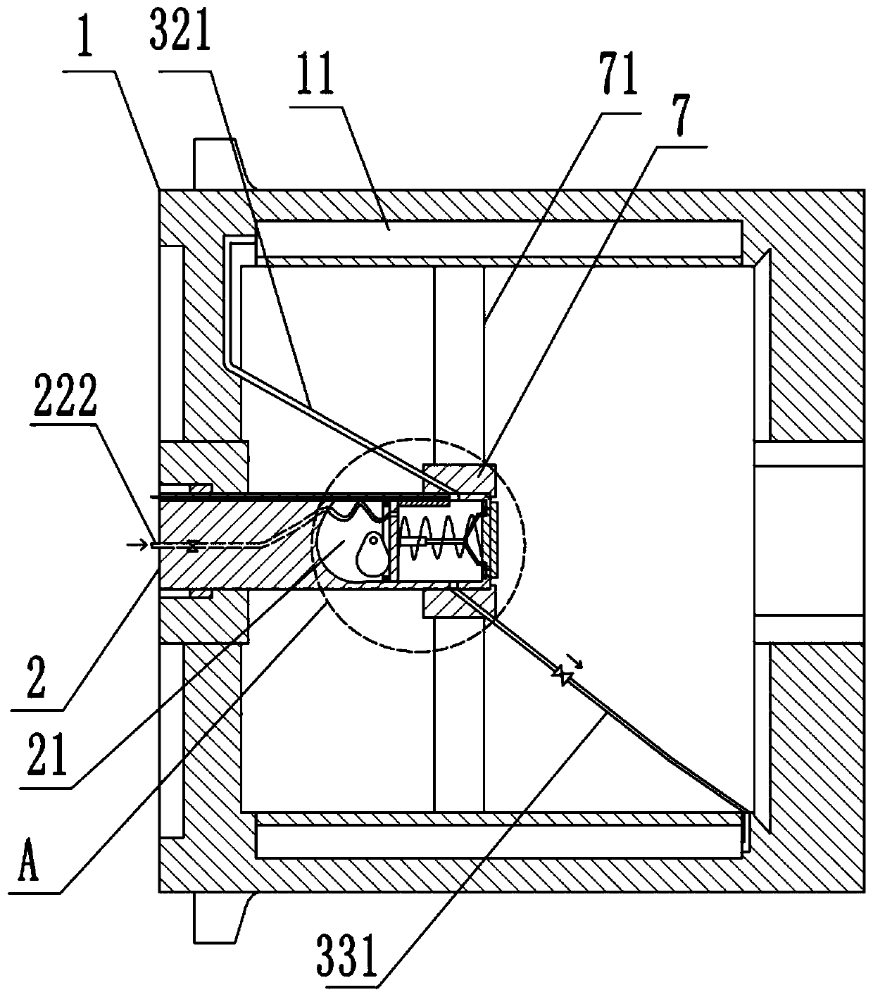
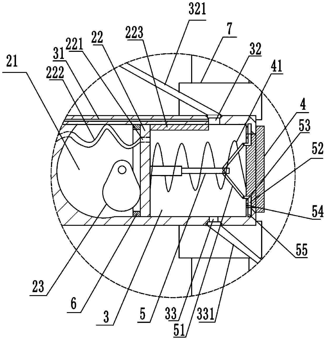
[0029] Basic as attached figure 1 with figure 2 As shown: the reel of the spray welding wire drawing machine with high wear resistance includes a reel body 1, and an annular cavity 11 is provided inside the wall of the reel body 1. There is also a positioning part inside the reel body 1 , the positioning part includes a mounting ring 7 and a support rod 71 , and the support rod 71 is fixed between the mounting ring 7 and the inner wall of the reel body 1 .

[0030] A mounting hole is provided on one side of the reel body 1 , and a columnar cooling part 2 is mounted in the mounting hole, and the end of the cooling part 2 protrudes into the mounting ring 7 . And the connection mode between the installation hole and the cooling part 2 is screw connection.

[0031] A cavity, a piston 22 and a cam 23 for moving the piston 22 are provided inside the cooling part 2 , the piston 22 is slidably connected in the cavity, and the piston 22 separates the cavity into a placement cavity 2...

Embodiment 2

[0044] The difference between this embodiment and the first embodiment is that, in order to facilitate the installation of the cooling part 2, an installation cavity is provided in the outer wall of the cooling part 2, and the motor is fixed in the installation cavity. The connection mode between the installation hole and the cooling part 2 is clamping; the details are as follows: the hole wall of the installation hole is provided with an L-shaped card slot, which specifically includes a vertical slot and a horizontal slot connected with the vertical slot; the cooling part 2 The outer wall is provided with a card protrusion for locking into the card slot; when installing, insert the cooling unit 2 from the installation hole until the card protrusion enters the vertical groove, and when the card protrusion moves to the junction of the vertical groove and the horizontal groove, turn Cooling part 2, so that the card protrusion enters the horizontal groove, that is, the installatio...


PUM


Abstract

The invention relates to the technical field of steel wire manufacturing, in particular to a spray welding wire drawing machine reel with high abrasive resistance. The spray welding wire drawing machine reel comprises a reel body, and an annular cavity is formed in the barrel wall of the reel body. A cooling part is arranged in the reel body, the cooling part includes a cavity, a piston and a cam,the piston divides the cavity into a placing cavity and a cooling cavity, and the cam is located in the placing cavity. A drainage channel is arranged in the cavity wall of the cooling cavity, and afirst through hole is formed in the cavity wall of the cooling cavity. A first water pipe communicating with the annular cavity is arranged on the first through hole. A second through hole is formed in the cavity wall of the cooling cavity, and a second water pipe communicating with the annular cavity is arranged on the second through hole. A water inlet hole is formed in the piston, and the waterinlet hole communicates with a water inlet pipe. A water retaining plate is arranged on the piston. An opening is further formed in the cavity wall of the cooling cavity, a sealing cover is arrangedat the opening, and a reset spring is arranged on the sealing cover. A locking piece is arranged in the cooling cavity. The spray welding wire drawing machine reel solves the problem that the heat exchange efficiency of the reel is reduced due to the fact that the inner wall of the reel is prone to scaling and being stained with mud in the prior art.

Description

technical field [0001] The invention relates to the technical field of steel wire manufacturing, and specifically discloses a reel of a spray welding wire drawing machine with high wear resistance. Background technique [0002] With the development of the metal products industry, high speed, high efficiency, low cost and strong process adaptability have become the pursuit goals of production enterprises. Wire drawing machine is a kind of mechanical equipment widely used in machinery manufacturing, metal processing, petrochemical industry, wire and cable and other industries. It is used to draw wire or rod to make the diameter, roundness, The internal metallographic structure, surface finish and straightening degree all meet the raw material processing requirements for the production of standard parts and other metal products. [0003] The reel of the wire drawing machine is a more important part of the wire drawing machine. The main function of the reel of the wire drawing ...

Claims


Application Information

Patent Timeline
Patent Type & Authority Patents(China)
IPC IPC(8): B21C1/14
Inventor 郑先延
Owner 遵义市润丰源钢铁铸造有限公司
Why Eureka
Try Eureka