High-speed rotor system of low-power-consumption magnetic suspension control moment gyroscope

A technology for controlling torque gyroscopes and high-speed rotors. It is applied in the directions of magnetic bearings, bearings, shafts and bearings. It can solve the problems of uncontrolled passive magnetic bearings, complex processing and assembly, and cumbersome assembly process, and achieve simple structure and parts processing technology. Simple, loss-reducing effect

Inactive Publication Date: 2018-06-22
BEIHANG UNIV
View PDF9 Cites 7 Cited by
  • Summary
  • Abstract
  • Description
  • Claims
  • Application Information

AI Technical Summary

Problems solved by technology

[0003] The CNKI document titled "Analysis and Research on Thermal-Structure Coupling of Magnetic Suspension Control Torque Gyroscope" uses active and passive magnetic bearings.
The CNKI document titled "A Low Disturbance Torque Three-DOF Spherical Magnetic Bearing" introduces a three-DOF spherical magnetic bearing. The contact surface between the stator and the rotor is a spherical envelope. Electromagnetic bearing, large loss
[0004] The rest of the CNKI literature on the magnetic levitation control torque gyro rotor mostly adopts the symmetrical permanent magnet bias radial magnetic bearing structure, which has a large loss and is difficult to assemble.
[0005] The Chinese patent literature with the authorization number CN104118579B provides a four-degree-of-freedom single-frame magnetic levitation control moment gyroscope. The rotor part is supported by a four-degree-of-freedom magnetic bearing. Its structure is relatively complicated and assembly is difficult.
The Chinese patent literature with the authorization number CN100538270C provides a double-frame magnetic levitation control moment gyroscope. The radial magnetic bearing part adopts a symmetrical hybrid magnetic bearing. A radial magnetic bearing assembly includes two magnetic bearing stators, and the magnetic poles are aligned. The assembly process is cumbersome and the loss is relatively high

Method used


Image

  • High-speed rotor system of low-power-consumption magnetic suspension control moment gyroscope
  • High-speed rotor system of low-power-consumption magnetic suspension control moment gyroscope
  • High-speed rotor system of low-power-consumption magnetic suspension control moment gyroscope

Examples


Embodiment Construction

[0018] In order to make the purpose, technical solution and advantages of the present invention clearer, the technical solution of the present invention will be clearly and completely described below in conjunction with specific embodiments of the present invention and corresponding drawings.

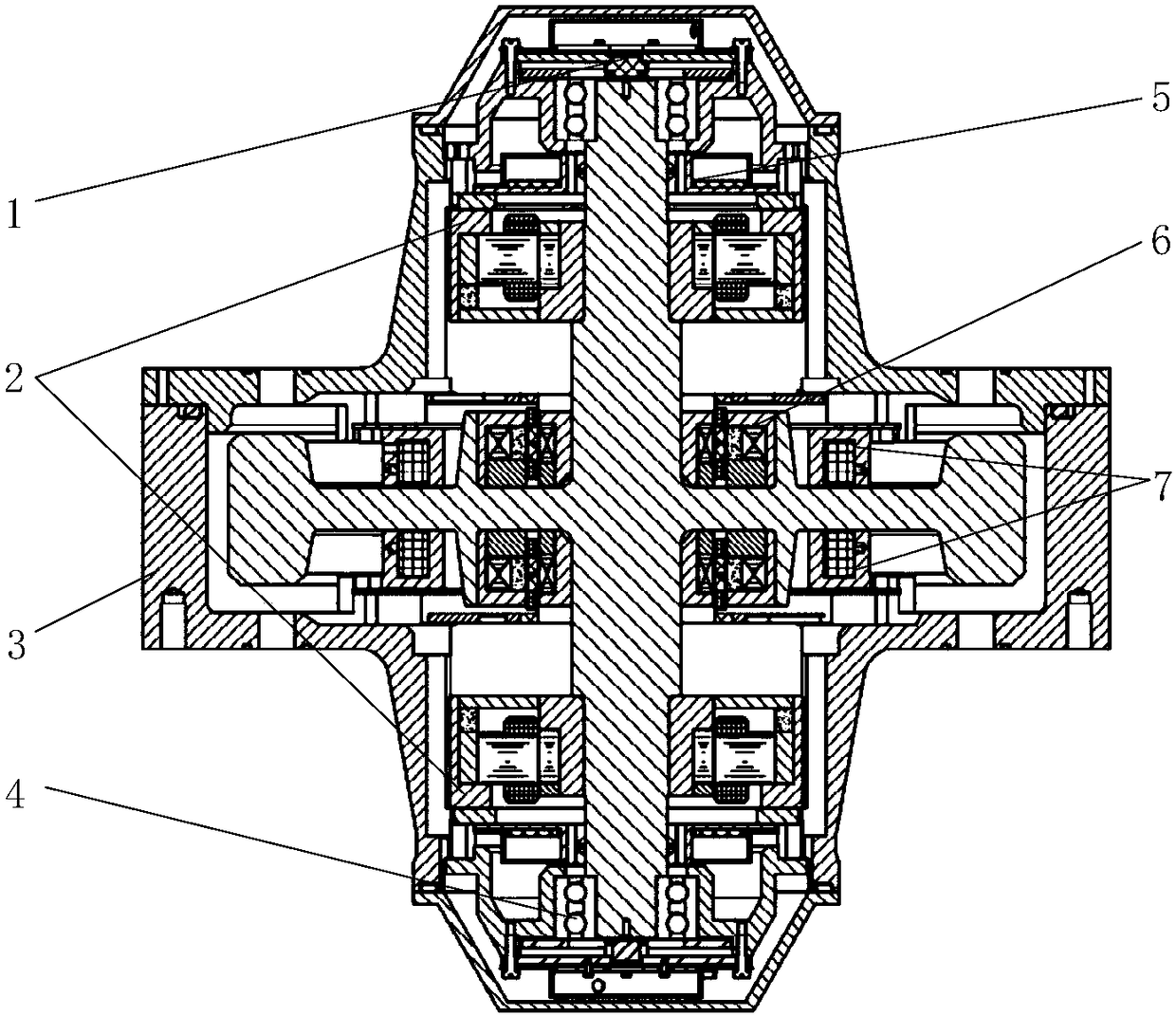
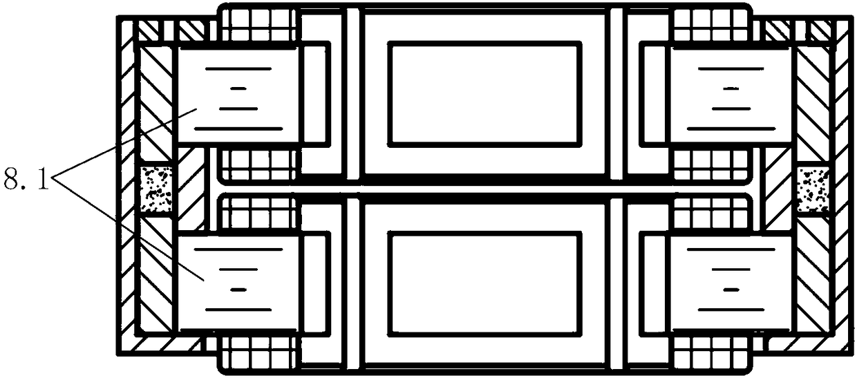
[0019] A low power consumption magnetic suspension control moment gyro high-speed rotor system designed by the present invention, the structure includes: axial sensor assembly 1, radial magnetic bearing stator assembly 2, gyro housing 3, protective bearing 4, radial sensor assembly 5, cup Type motor 6, axial magnetic bearing stator assembly 7;

[0020] The radial magnetic bearing stator assembly 2 adopts a hybrid magnetic bearing scheme to achieve the goals of reducing mass, reducing loss, increasing output torque, and simple and reliable assembly process.

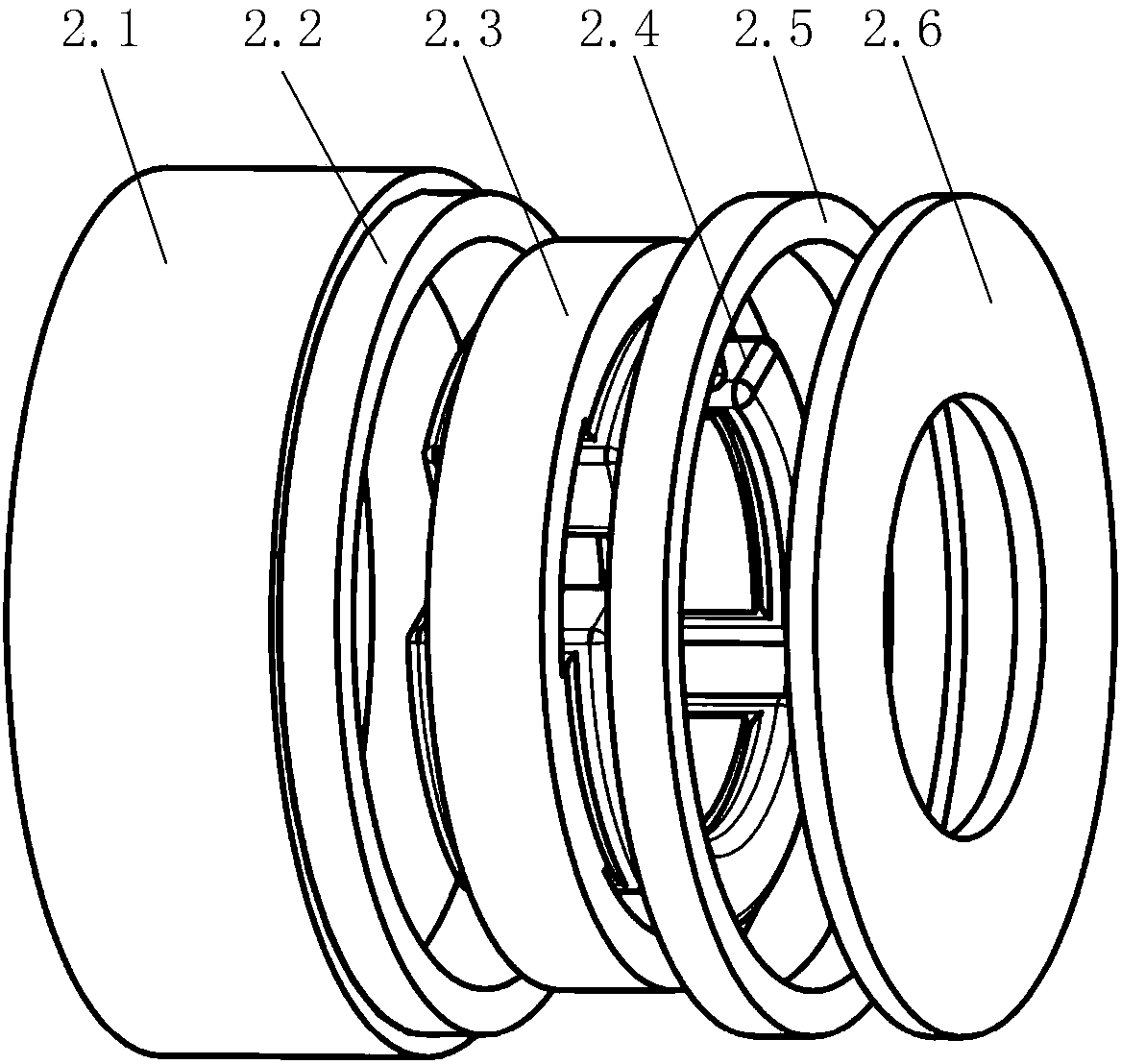
[0021] Wherein, the radial magnetic bearing stator assembly 2 is a homopolar asymmetric permanent magnet bias radial magnetic bear...


PUM


Abstract

The invention discloses a high-speed rotor system of a low-power-consumption magnetic suspension control moment gyroscope. The high-speed rotor system comprises radial magnetic bearing stator assemblies, an axial magnetic bearing stator assembly, a cup type motor, a radial sensor assembly, an axial sensor assembly, a protection bearing and a gyroscope room. A mixed magnetic bearing scheme is adopted by the radial magnetic bearing stator assemblies. Each radial magnetic bearing stator assembly comprises a sleeve, a radial magnetic bearing stator, a coil, a permanent magnet, a bias magnetic ringand a guide magnetic ring. The radial magnetic bearing scheme of the structure is adopted by the rotor system, and the rotor system has the advantages that the mass is small, losses are low, the structure is simple, and the assembly process is simple and reliable.

Description

technical field [0001] The invention relates to the technical field of designing magnetic suspension bearings, and in particular relates to a low-power consumption magnetic suspension control torque gyro high-speed rotor system. Background technique [0002] Magnetic suspension bearings have the advantages of no mechanical friction, no lubrication, high rotor speed, long life, and high reliability. They are widely used in molecular pumps, blowers, flywheels, and control torque gyroscopes. Among them, the high-speed rotor system that controls the moment gyroscope is supported by magnetic suspension bearings, which can realize the characteristics of no mechanical friction and no lubrication. [0003] The CNKI document titled "Analysis and Research on Thermal-Structure Coupling of Magnetic Suspension Control Torque Gyroscope" uses active and passive magnetic bearings. The CNKI document titled "A Low Disturbance Torque Three-DOF Spherical Magnetic Bearing" introduces a three-DO...

Claims


Application Information

Patent Timeline
IPC IPC(8): F16C32/04
CPCF16C32/0446F16C32/047F16C32/0474
Inventor 韩邦成张益明郑世强李海涛刘刚陈诚
Owner BEIHANG UNIV
Why Eureka
Try Eureka