
Brake pad wear condition detection system and method

A detection system and brake pad technology, applied in the direction of brake safety system, brake type, mechanical equipment, etc., can solve problems such as increased cost, hidden safety hazards, and difficulty in timely discovery, and achieve low long-term use costs, accurate detection results, and improved The effect of reliability

Pending Publication Date: 2018-06-22
SINO TRUK JINAN POWER
View PDF10 Cites 6 Cited by
  • Summary
  • Abstract
  • Description
  • Claims
  • Application Information

AI Technical Summary

Problems solved by technology

[0004] (1) Specially produced brake pads are required, which has poor versatility and increases costs;
[0005] (2) The sensor only has a qualitative alarm and cannot display the wear status in real time;
[0006] (3) Lack of real-time monitoring, the reliability of the detection device itself is difficult to guarantee, even if it fails, it is difficult to find it in time, and it is easy to bring safety hazards

Method used


Image

  • Brake pad wear condition detection system and method
  • Brake pad wear condition detection system and method
  • Brake pad wear condition detection system and method

Examples


Embodiment Construction

[0036] The present invention will be further described below in conjunction with the accompanying drawings and embodiments.

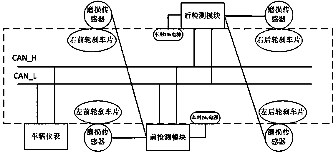
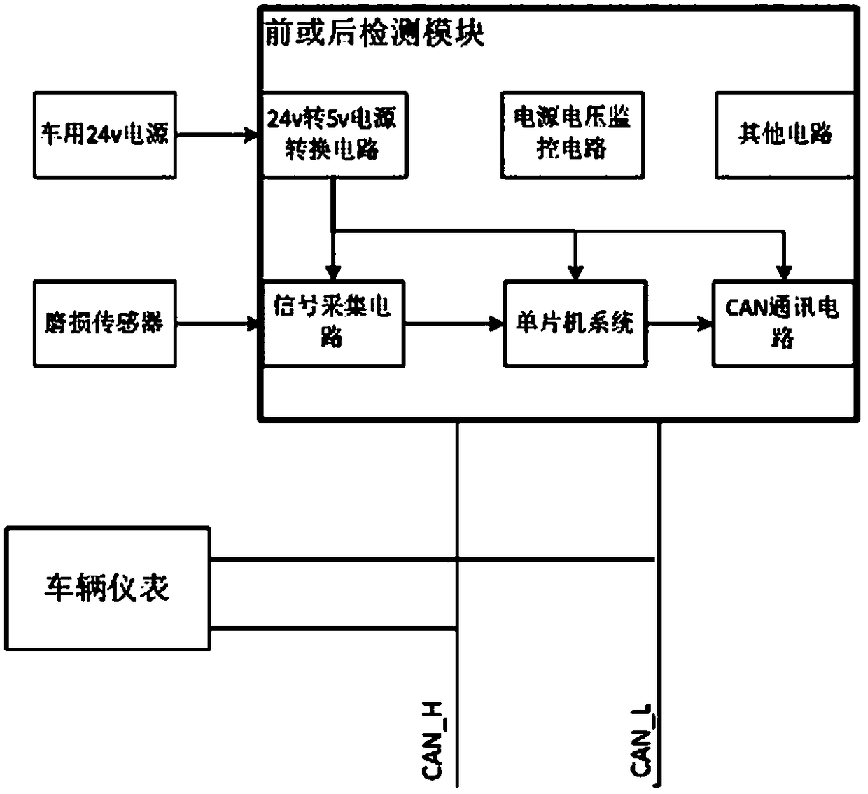
[0037] like Figure 1 to Figure 3 As shown, the present embodiment is a brake pad wear detection system, including:

[0038] 4 wear sensors, 24V power supply for vehicle, front detection module, rear detection module, vehicle CAN bus, vehicle instrument;

[0039] Wherein, the four wear sensors are respectively mounted on the drum brakes of the left wheel of the front axle, the right wheel of the front axle, the left wheel of the rear axle, and the right wheel of the rear axle, and are angle sensors for measuring the angle of the self-adjusting arm of the axle brake; Specifically, the BRASS LINING WEAR SENSOR produced by Haldex Company has 4 terminals, which are 1 5V power input terminal, 2 signal output terminals, and 1 ground terminal; the basic principle is that the brake pads wear more More, the larger the axle brake self-adjusting arm angle is, th...


PUM


Abstract

The invention relates to a brake pad wear condition detection system and method. The brake pad wear condition detection system comprises four wear sensors, a vehicle 24V power supply, a front detection module, a rear detection module, a vehicle CAN bus and a vehicle instrument; and the front detection module and the rear detection module are correspondingly used for collecting and processing signals sent by the wear sensors of the left and right wheels of a front axle and the left and right wheels of a rear axle, and send the state values obtained after the signals processed by the CAN bus tothe vehicle instrument for display. The brake pad wear condition detection method comprises six steps of power supply, measurement, signal transmission, signal processing, signal sending and display.According to the brake pad wear condition detection system and the method, the thickness state information of the brake pad is obtained by measuring the rotation angle of the vehicle axle brake self-adjusting arm, so that the universality is good and long-term use cost is low; the CAN bus is used for periodic communication, the state values are displayed by the vehicle instrument continuously, notonly can real-time display be realized, but also the faults of the detection system can be discovered in time to avoid hidden dangers.

Description

technical field [0001] The invention relates to a brake pad wear condition detection system and method, belonging to the field of auto parts and application methods. Background technique [0002] GB7258 clearly stipulates that the brakes of passenger cars, trucks and special operation vehicles with a total mass greater than 3500Kg should be equipped with automatic brake clearance adjustment devices. In practical applications, once the brakes fail to cause large losses for this type of vehicle, the requirements for brake safety are also relatively high. In order to prevent brake failure due to excessive wear of the brake pads, a device that detects the degree of wear of the brake pads and sends an alarm when the brake pads need to be replaced has emerged. The brake pad detection device in the prior art usually adopts sensors buried inside the brake pads, and uses the phenomenon that the sensors are exposed and rubbed after the brake pads are worn to detect and alarm. [000...

Claims


Application Information

Patent Timeline
Patent Type & Authority Applications(China)
IPC IPC(8): F16D66/02B60T17/22
CPCF16D66/026F16D66/027B60T17/22
Inventor 张文斌张兰兰秦延隆韩庆福
Owner SINO TRUK JINAN POWER
Learn More