Oscillating bar oscillating tooth speed reducer with clearance eliminating mechanism

A movable tooth reducer and backlash elimination technology, applied in the direction of gear vibration/noise attenuation, mechanical equipment, gear transmission, etc., can solve the problems of generating axial force, impact, affecting transmission performance, etc. The effect of precise clearance adjustment

Active Publication Date: 2018-06-22
BEIJING XINGHANG MECHANICAL ELECTRICAL EQUIP
View PDF7 Cites 11 Cited by
  • Summary
  • Abstract
  • Description
  • Claims
  • Application Information

AI Technical Summary

Problems solved by technology

However, due to the wear of the meshing pair during the transmission process of the movable gear, the meshing gap is generated and vibration and impact are also caused, which affects its transmission performance.
[0003] The Chinese patent with the application number 01108707.2, "Space Cam Movable Tooth Transmission Device", the space cam movable tooth meshing pair is composed of end teeth, movable gear racks, ball movable teeth, space cams and adjusting gaskets. Adjust the meshing gap, and use the error equalization effect of the multi-teeth meshing of the movable tooth transmission to realize the precise transmission, but this device cannot realize the backlash elimination for each movable tooth at the same time, and because of the one-tooth difference, the mechanism has inertial force and one-way workload
"Research on Automatic Backlash Elimination Swing Rod Movable Teeth Transmission" published in Mechanical Design Journal, Vol. The oscillating method eliminates the radial clearance of the meshing pair. This method realizes the simultaneous elimination of the wear clearance of all the meshing pairs, but it cannot simultaneously eliminate the backlash for each movable tooth, and generates axial force, which affects its transmission performance.

Method used


Image

  • Oscillating bar oscillating tooth speed reducer with clearance eliminating mechanism
  • Oscillating bar oscillating tooth speed reducer with clearance eliminating mechanism
  • Oscillating bar oscillating tooth speed reducer with clearance eliminating mechanism

Examples


Embodiment Construction

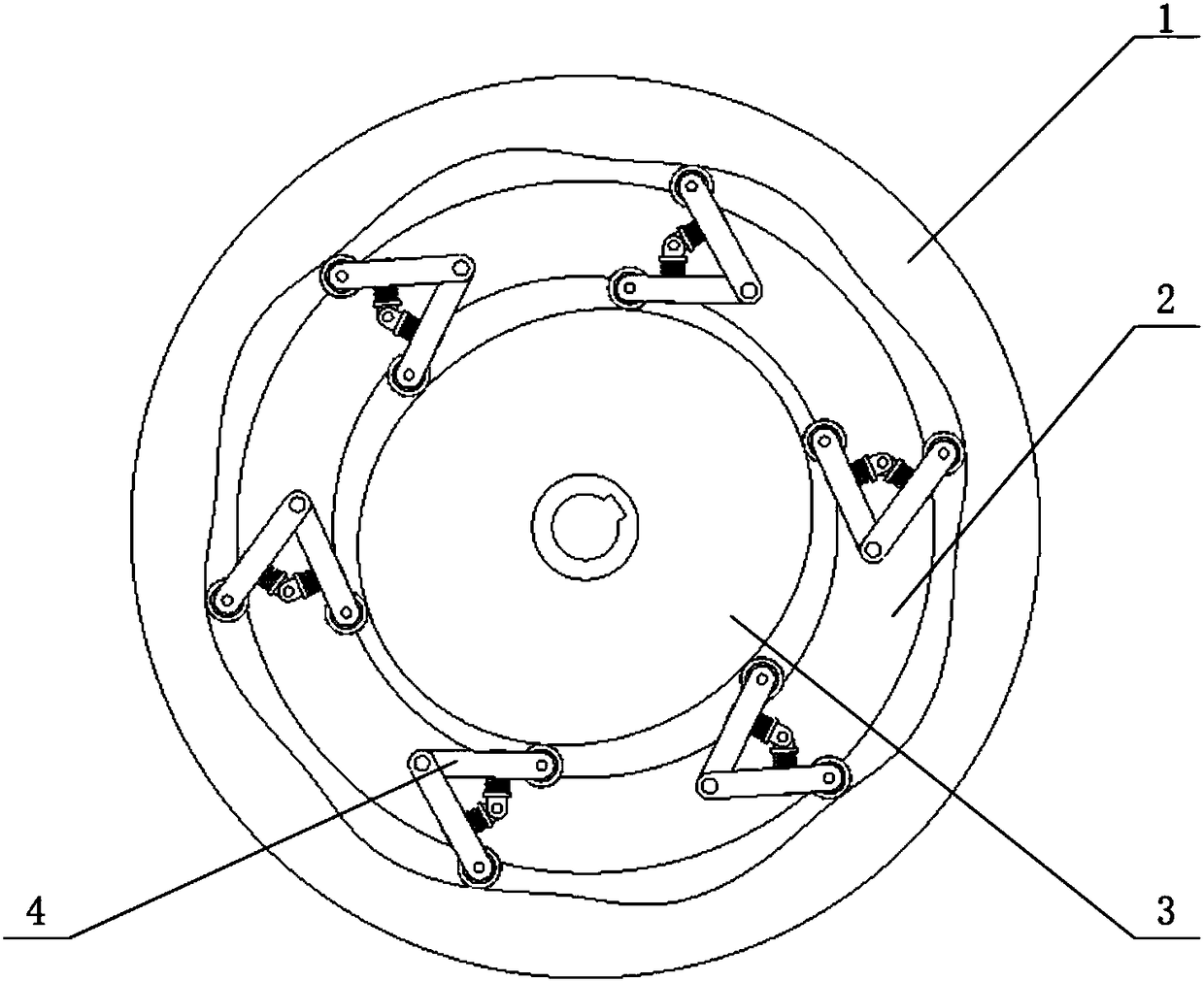
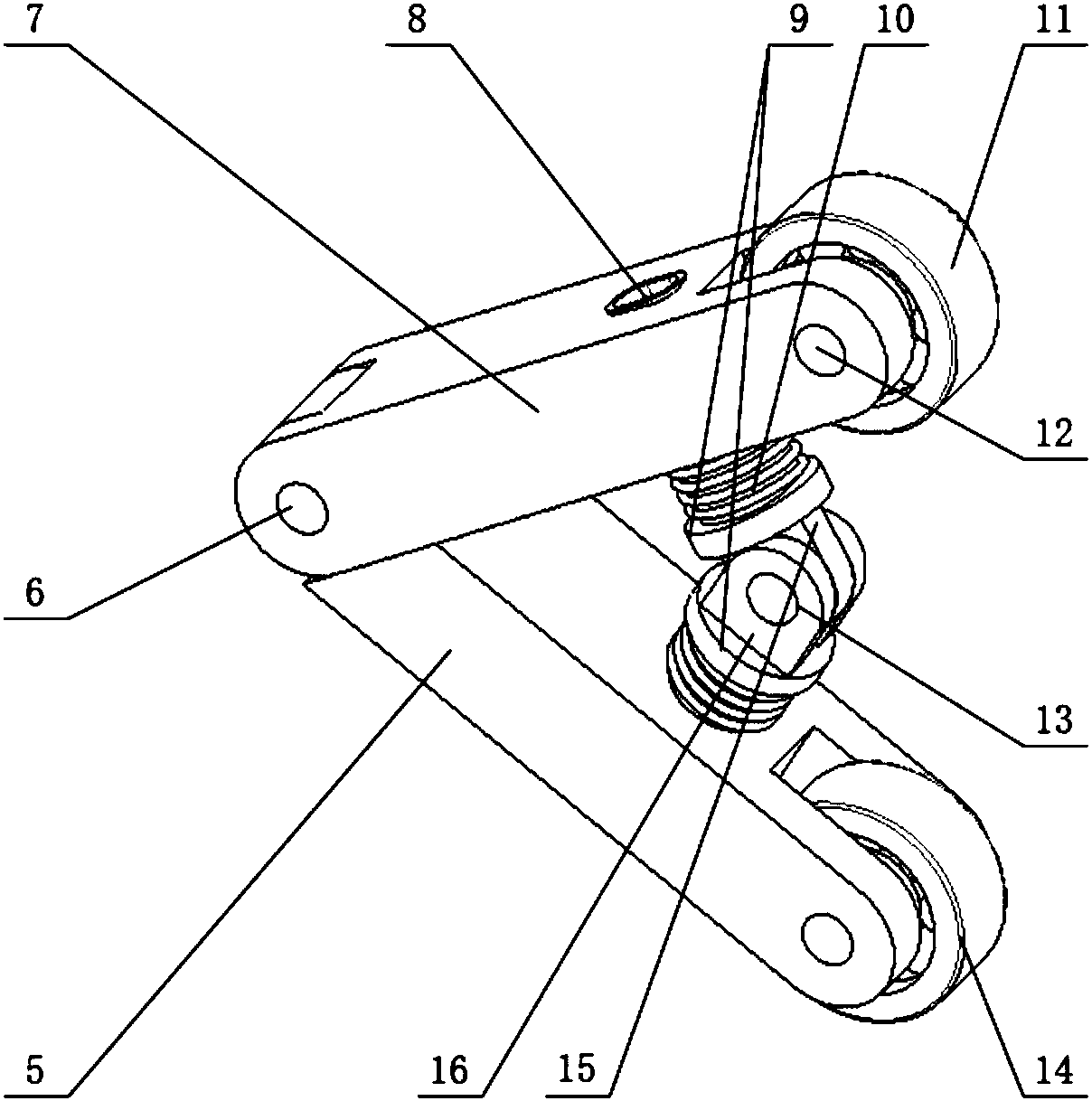
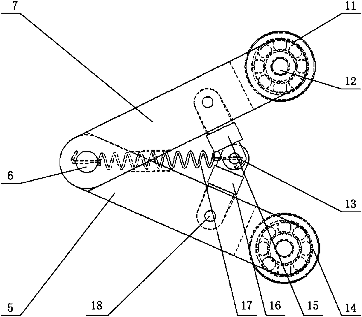
[0013] exist figure 1 In the schematic diagram of the front view of the swing rod movable tooth reducer with the anti-backlash mechanism shown, the center wheel 1 is a disc with a central through hole, and one end surface is provided with a groove, and the inner wall of the groove is in the shape of a tooth. The center through hole is provided with an elliptical shock wave device 3 coaxial with it and the outer end face is flush with the end face of the center wheel, and the end face is lower than the center at the position between the inner tooth profile of the center wheel and the outer peripheral surface of the shock wave device. Wheel end face and internal diameter are greater than the large diameter of the shock wave device, the outer diameter is less than the annular movable gear frame 2 of internal tooth profile, be provided with 6 evenly distributed swing rod movable teeth 4 on this movable gear frame. The movable tooth of the swing rod mainly includes an upper member ...


PUM


Abstract

The invention discloses an oscillating bar oscillating tooth speed reducer with a clearance eliminating mechanism. A center through hole of a center wheel of the oscillating bar oscillating tooth speed reducer is provided with an oval shock wave device coaxial to the center wheel. The position between the inner tooth profile of the center wheel and the peripheral face of the shock wave device is provided with an annular oscillating tooth frame, wherein the end face of the annular oscillating tooth frame is lower than the end face of the center wheel, the inner diameter of the annular oscillating tooth frame is larger than the major diameter of the shock wave device, and the outer diameter of the annular oscillating tooth frame is smaller than the inner tooth profile. The oscillating toothframe is provided with 3-6 evenly-distributed oscillating bar oscillating teeth. Each oscillating bar oscillating tooth comprises an upper component, a lower component, an upper inner component, a lower inner component and an elastic assembly. According to the adopted oscillating bar oscillating teeth, resilience generated due to spring elastic deformation can be used for automatically adjusting the relative distance between upper wheels and lower wheels of the oscillating bar oscillating teeth, impacts and vibration generated by an oscillating tooth gear in the running state during clearanceeliminating are eliminated, and the effects of buffering and vibration absorbing are achieved. According to the adopted oscillating bar oscillating teeth, accurate clearance adjustment can be achievedfor response of electrostriction elements to electric signals, and the situation of influences on the transmission performance due to the clearance generated due to abrasion and other reasons is greatly improved.

Description

technical field [0001] The invention relates to a swing rod movable tooth reducer. Background technique [0002] Movable gear reducer is a new type of reducer that can be used to transmit rotary motion between two coaxial shafts. The structure of a typical movable tooth transmission includes: a push rod movable tooth, a swing movable tooth, a ball movable tooth and a sleeve movable tooth, etc. Swing rod movable tooth transmission is a planetary transmission with multiple teeth simultaneously meshing and less tooth difference evolved on the basis of swing movable tooth transmission. It has high bearing capacity, good basic component craftsmanship, short kinematic chain and compact structure, etc. advantage. However, due to the wear and tear of the meshing pair during the transmission process of the movable gear, the meshing gap is generated, and vibration and impact are also caused, which affects its transmission performance. [0003] The Chinese patent with the applicatio...

Claims


Application Information

Patent Timeline
Patent Type & Authority Applications(China)
IPC IPC(8): F16H49/00F16H1/32F16H57/12
CPCF16H1/2863F16H49/001F16H57/0006F16H2001/328F16H2057/123F16H2057/127
Inventor 宜亚丽贺雷李恒金贺荣
Owner BEIJING XINGHANG MECHANICAL ELECTRICAL EQUIP
Why Eureka
Try Eureka