

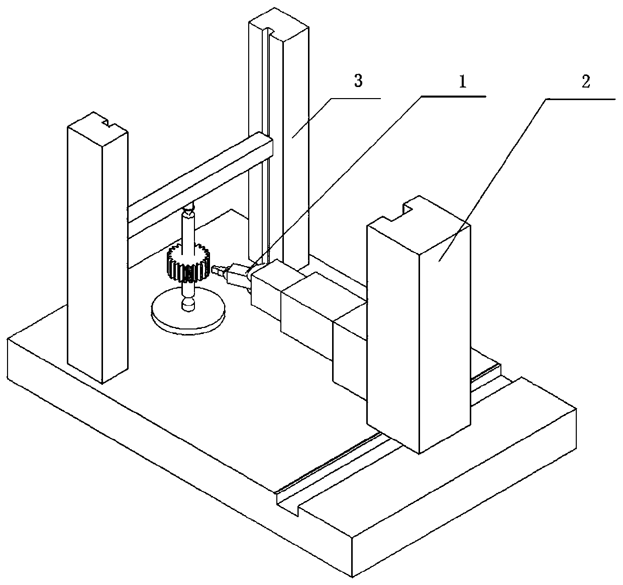
A six-axis laser gear measuring device
A gear measurement, six-axis technology, applied in the direction of measuring devices, optical devices, radio wave measurement systems, etc., can solve the problems that the detector cannot receive reflected light, can not effectively obtain data, and the measurement speed is slow, so as to overcome the radius Compensation, avoiding the problem of measuring dead angle, and improving the effect of accuracy
- Summary
- Abstract
- Description
- Claims
- Application Information
AI Technical Summary
Problems solved by technology
Method used
Image

Examples
Embodiment 1
[0045] Such as Figure 5 As shown, the specific implementation of the cylindrical spur gear measurement using the present invention is realized through the following steps.
[0046] The first step is to reset the system. The six-axis movement is driven by the control system to drive the servo motor. The linear movement of the X-axis drives the Y, Z, α, and β-axis to move forward and backward along the X-axis, and the up-and-down movement of the Y-axis drives the Z, α, and β-axis to move up and down along the Y-axis. , the telescopic movement of the Z axis drives the α and β axes to move back and forth along the Z axis, and the rotation of the α axis drives the β axis to rotate around the α axis. The six-axis coordinate information is obtained through the grating signal corresponding to each axis, the six-axis reset is realized, and the coordinate system corresponding to the motion system is found.
[0047] The second step is to install the gears. Connect the cylindrical spu...
Embodiment 2
[0053] Such as Image 6 As shown, the specific implementation of bevel gear measurement using the present invention is realized through the following steps.
[0054] The first step is to reset the system. The servo motor is driven by the control system to operate the six-axis movement. The linear movement of the X-axis drives the Y, Z, α, and β-axis to move forward and backward along the X-axis, and the up-and-down movement of the Y-axis drives the Z, α, and β-axis to move up and down along the Y-axis. , the telescopic movement of the Z axis drives the α and β axes to move back and forth along the Z axis, and the rotation of the α axis drives the β axis to rotate around the α axis. The six-axis coordinate information is obtained through the grating signal corresponding to each axis, the six-axis reset is realized, and the coordinate system corresponding to the motion system is found.
[0055] The second step is to install the gears. Connect the bevel gear to be tested with ...
PUM
 Abstract
Description
Claims
Application Information