
Test tube freezer

A freezer and test tube technology, applied in the direction of test tube supports/clamps, heating or cooling equipment, laboratory utensils, etc. The overall structure is simple and the heat transfer is stable.

Pending Publication Date: 2018-06-29
ZHEJIANG HELI REFRIGERATION EQUIP
View PDF0 Cites 0 Cited by
  • Summary
  • Abstract
  • Description
  • Claims
  • Application Information

AI Technical Summary

Problems solved by technology

But the existing test tube freezing and preservation device generally adopts copper tubes to surround the container, and the cold energy is transmitted to the container by the copper tube, then to the test tube rack by the container, and then to the test tube by the test tube rack. Low freezing efficiency

Method used


Image

  • Test tube freezer
  • Test tube freezer
  • Test tube freezer

Examples


Embodiment Construction

[0024] The following will clearly and completely describe the technical solutions in the embodiments of the present invention with reference to the accompanying drawings in the embodiments of the present invention. Obviously, the described embodiments are only some, not all, embodiments of the present invention. Based on the embodiments of the present invention, all other embodiments obtained by persons of ordinary skill in the art without making creative efforts belong to the protection scope of the present invention.

[0025] The object of the present invention is to provide a test tube freezer to solve the problems in the prior art, shorten the refrigerant transfer route, and improve the efficiency of test tube refrigeration.

[0026] In order to make the above objects, features and advantages of the present invention more comprehensible, the present invention will be further described in detail below in conjunction with the accompanying drawings and specific embodiments.

...


PUM


Abstract

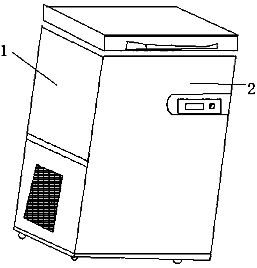
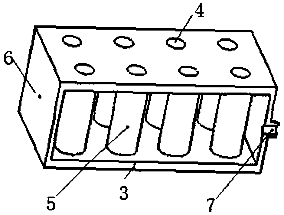
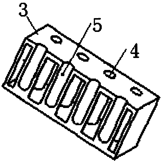
The invention discloses a test tube freezer which comprises an outer body and a refrigeration system located in the outer body, wherein an evaporator is mounted in the outer body; at least one test tube hole is formed in a top plate of the evaporator; the test tube holes are tightly connected with test tube racks; the test tube racks are located in the evaporator; a liquid refrigerant inlet is formed at one end of the evaporator; a gas refrigerant outlet is formed at the other end of the evaporator; and the refrigerant inlet and the refrigerant outlet are connected with the refrigeration system. The effective evaporation capacity of the novel evaporator of the test tube freezer is large; the gasification efficiency of a liquid refrigerant is high; the refrigeration capacity power is large;the heat exchange area between test tubes and the refrigerant is large; the evaporator directly provides test tube refrigeration capacity; a refrigeration capacity transfer path of the refrigerant isshortened; and the refrigeration efficiency of the test tubes is improved.

Description

technical field [0001] The invention relates to the technical field of test tube freezing, in particular to a test tube freezing box. Background technique [0002] Test tubes are often used to hold various reagents or specimens, and the products in the test tubes often need to be frozen during production, transportation or experimentation. In the existing test tube cryopreservation technology, the test tube is often placed in a container, and the container is evaporatively refrigerated by a refrigerant, thereby indirectly realizing the cryopreservation of the test tube. But the existing test tube freezing and preservation device generally adopts copper tubes to surround the container, and the cold energy is transmitted to the container by the copper tube, then to the test tube rack by the container, and then to the test tube by the test tube rack. Freezing efficiency is low. Contents of the invention [0003] The object of the present invention is to provide a test tube ...

Claims


Application Information

Patent Timeline
IPC IPC(8): B01L9/06B01L7/00
CPCB01L7/50B01L9/06B01L2300/1894
Inventor 章标仂钱宏华潘晓林周建
Owner ZHEJIANG HELI REFRIGERATION EQUIP
Learn More