Painting device for valve handwheel

The technology of a painting device and hand wheel is applied to the device and coating of the surface coating liquid, which can solve the problems of backward processing method, low processing efficiency and increased workload, so as to speed up painting efficiency and improve processing. Quality, the effect of preventing the paint layer from being too thick

Inactive Publication Date: 2018-06-29
CHONGQING QIANYAN MACHINERY CO LTD
View PDF0 Cites 5 Cited by
  • Summary
  • Abstract
  • Description
  • Claims
  • Application Information

AI Technical Summary

Problems solved by technology

In the prior art, the painting processing methods of the handwheel mainly include two types, one is to use a paint brush to avoid the perforation and paint evenly on the handwheel, this kind of processing method is relatively backward, the workload of the workers is heavy, and the processing efficiency is low , which is not conducive to production. Another way is to directly place the handwheel in the paint box and paint by dipping. However, a large amount of paint will remain in the perforation, which makes it difficult for the valve stem to pass through when installing the valve stem. The hole is fixed to the hand wheel, so in the subsequent processing, it is necessary to remove the paint from the hole, which undoubtedly leads to an increase in workload

Method used


Image

  • Painting device for valve handwheel
  • Painting device for valve handwheel
  • Painting device for valve handwheel

Examples


Embodiment Construction

[0020] The present invention will be further described in detail below through specific implementations:

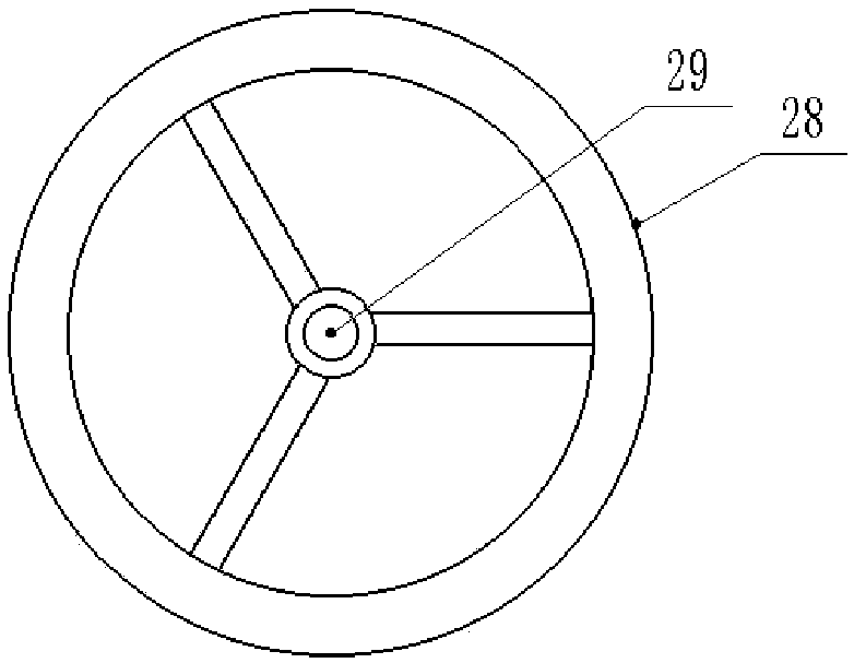
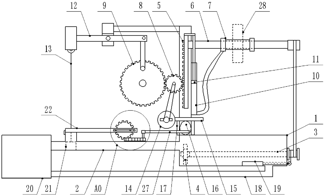
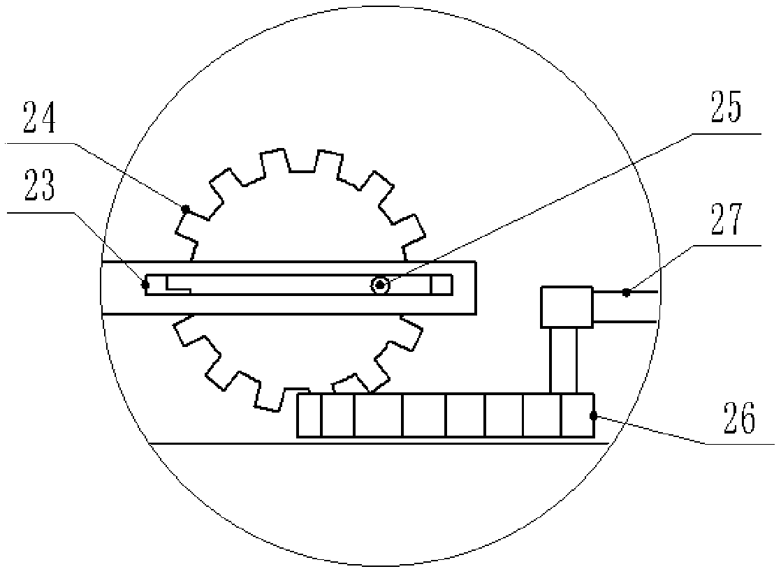
[0021] The reference signs in the drawings of the specification include: paint tank 1, paint inlet pipe 2, rotating shaft 3, turbine 4, rack 5, cross bar 6, elastic inflatable cylinder 7, pinion 8, large gear 9, vertical tube 10, Piston 11, lever 12, sling 13, fan 14, blowing pipe 15, air bag 16, vertical plate 17, paint discharge pipe 18, baffle 19, return box 20, gate 21, end cover 22, chute 23, first Gear 24, clamping column 25, second gear 26, push rod 27, hand wheel 28, and perforation 29.

[0022] This example figure 2 As shown, a painting device for a valve handwheel includes a paint tank 1, a paint inlet pipe 2 is connected to the left end of the paint tank 1, a branch pipe is welded on the paint inlet pipe 2, and a gate 21 is slidably connected to the paint inlet pipe 2. The gate 21 is located at the connecting port of the branch pipe and the paint inlet pipe 2 and ...


PUM


Abstract

The invention relates to the field of valve production, and discloses a painting device for a valve handwheel. The painting device comprises a paint groove; a rack is arranged on the paint groove; a rack is slidably connected onto the rack; a small gear is meshed with the rack; a cross rod is rotatably connected to the rack; a fixed position is arranged on the cross rod; the fixed position is sleeved with an elastic inflation barrel; a vertical pipe is arranged on the rack; a piston which is in clearance fit with the vertical pipe is arranged in the vertical pipe; the inside of the vertical pipe is divided into an upper pipeline and a lower pipeline by the piston; a connection rod is arranged in the upper pipeline; two ends of the connection rods are separately hinged to the rack and the piston; an inflation pipe is connected between a lower end of the lower pipeline and the elastic inflation barrel; a paint inlet pipe is connected with the paint groove; a rotary shaft is rotatably connected into the paint groove; a turbine is fixedly connected to one end of the rotary shaft and is located at a connection opening of the paint inlet pipe and the paint groove; and an elastic belt isconnected between the other end of the rotary shaft and the cross rod. By adopting the painting device, while the handwheel is painted, a through hole of the handwheel is prevented from being paintedwith paint; and machining efficiency of the handwheel is improved.

Description

Technical field [0001] The invention relates to the field of valve production and processing, in particular to a painting device for a valve hand wheel. Background technique [0002] The valve is a control component in the fluid conveying system, which has the functions of cut-off, regulation, diversion, prevention of backflow, stabilization, diversion or overflow and pressure relief. The main structure of the valve includes the valve body, the valve core, the valve stem and the handwheel. The valve has a T-shaped structure as a whole, and the valve body has an "I"-shaped structure, and the valve body includes an intermediate pipe and a connection at both ends of the intermediate pipe. Flange, the flange is provided with multiple positioning holes evenly distributed in the circumferential direction, and the handwheel is like figure 1 As shown, it includes a wheel ring and a connecting column in the wheel ring. The center of the connecting column is provided with a perforation for...

Claims


Application Information

Patent Timeline
Patent Type & Authority Applications(China)
IPC IPC(8): B05C3/10B05C9/12B05C11/08B05C11/10B05C11/115B05C13/02B05C21/00
CPCB05C3/10B05C9/12B05C11/08B05C11/10B05C11/1039B05C11/115B05C13/02B05C21/005
Inventor 罗贵良
Owner CHONGQING QIANYAN MACHINERY CO LTD
Why Eureka
Try Eureka