Continuous-lubrication extrusion mold

A technology for extrusion dies and lubricants, applied in the direction of metal extrusion dies, etc., can solve problems such as poor lubrication effect, increased cost and difficulty of mold manufacturing, and wear and tear of the coating on the surface of the mold, so as to avoid coarse crystal ring defects and improve Effect of surface quality, continuous and stable lubrication

Inactive Publication Date: 2018-06-29
HARBIN INST OF TECH
View PDF5 Cites 6 Cited by
  • Summary
  • Abstract
  • Description
  • Claims
  • Application Information

AI Technical Summary

Problems solved by technology

[0004] The present invention aims to solve the problem that the lubricating effect is not good when the lubricant is applied on the surface of the mold and the billet during extrusion, and the method of coating the surface of the mold increases the manufacturing cost and difficulty of the mold, and the coating on the surface of the mold is easy to gradually lose The technical problem of wear and tear, while providing a continuously lubricated extrusion die

Method used


Image

  • Continuous-lubrication extrusion mold
  • Continuous-lubrication extrusion mold
  • Continuous-lubrication extrusion mold

Examples


specific Embodiment approach 1

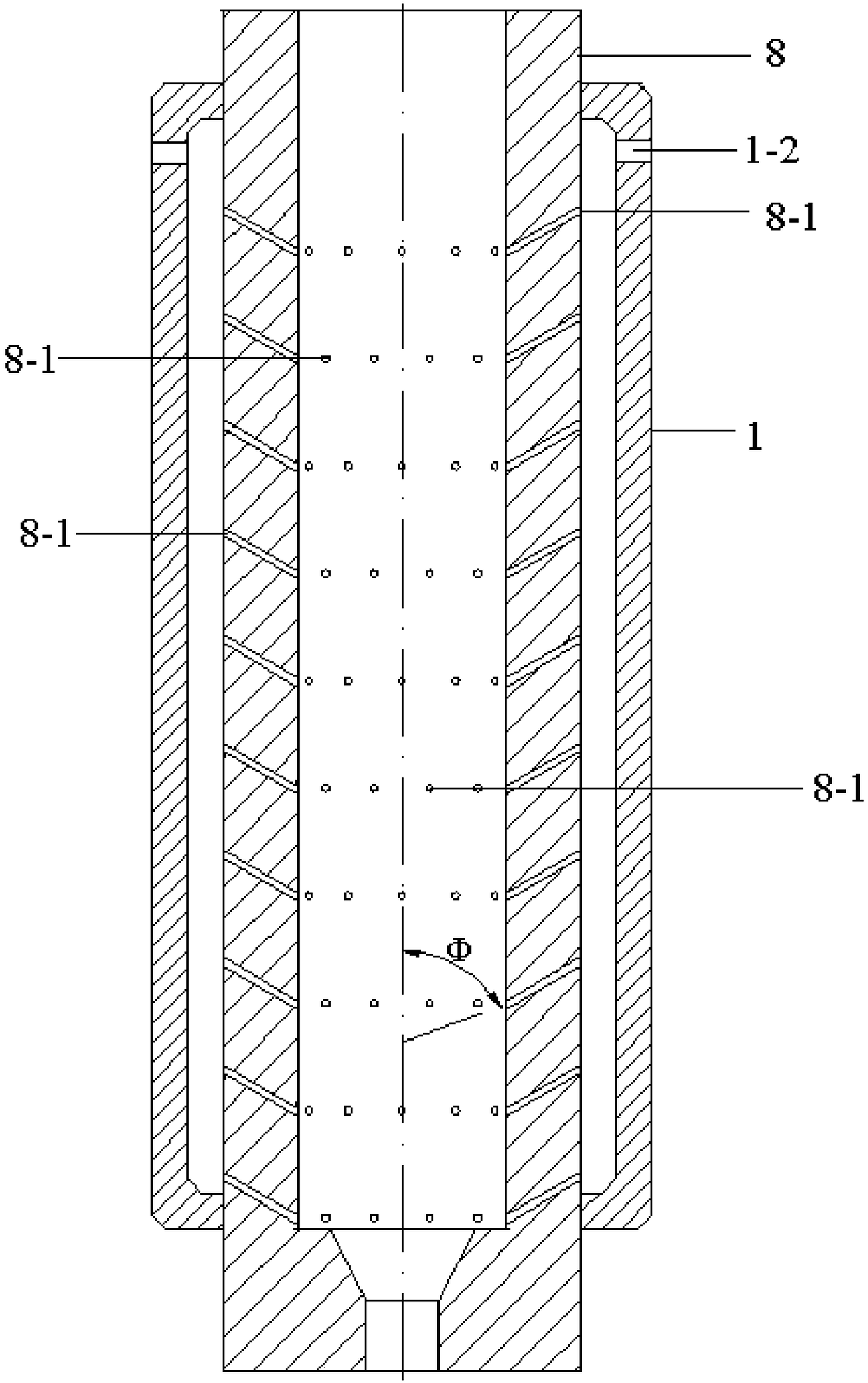
[0025] Specific embodiment one: this embodiment is a continuous lubricated extrusion die, such as figure 1 , specifically composed of a lubricant storage tank 1 and an extrusion die 8;

[0026] The lubricant storage tank 1 is a hollow structure, and at least one first lubricant injection hole 1-2 is arranged on the upper part of the side wall of the lubricant storage tank 1. The first lubricant injection hole 1-2 is a through hole, and the first lubrication The lubricant injection hole 1-2 communicates with the inside of the lubricant storage tank 1;

[0027] At least one lubricant hole 8-1 is arranged on the side wall of the extrusion die 8, the lubricant hole 8-1 is a through hole, and the lubricant hole 8-1 communicates with the inside of the extrusion die 8; the lubricant hole 8 The angle Φ between -1 and the vertical axis is 30°~90°;

[0028] The lubricant storage tank 1 is set on the outside of the extrusion die 8, and the contact between the upper end surface and the ...

specific Embodiment approach 2

[0035] Embodiment 2: This embodiment differs from Embodiment 1 in that: the diameter of the lubricant hole 8 - 1 is 0.1 mm to 5 mm. Others are the same as the first embodiment.

specific Embodiment approach 3

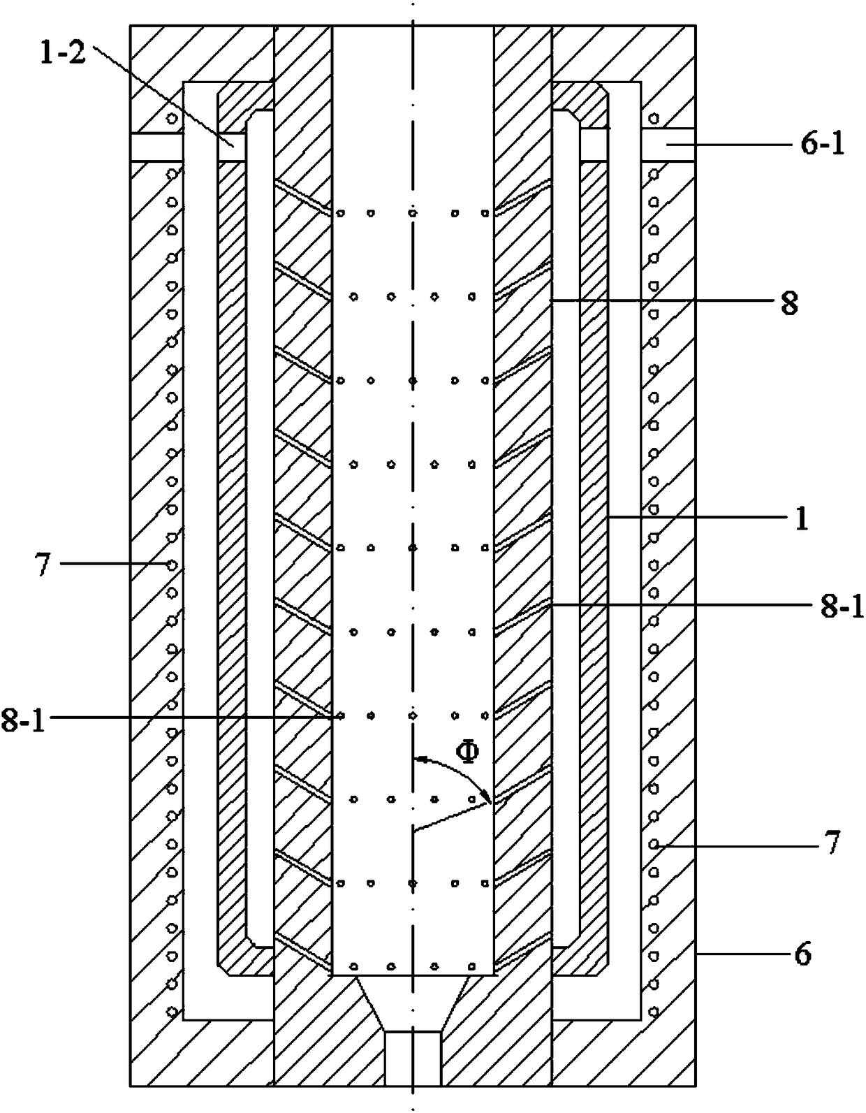
[0036] Specific implementation mode three: the difference between this implementation mode and specific implementation mode one or two is: if figure 2 , the outer wall of the lubricant storage tank 1 is covered with a thermal insulation cover 6, and the upper part of the side wall of the thermal insulation cover 6 is provided with at least one second lubricant injection hole 6-1, and the second lubricant injection hole 6-1 is a through hole; At least one heating resistance wire 7 is arranged in the heat preservation cover 6 . Others are the same as those in Embodiment 1 or 2.


PUM

PropertyMeasurementUnit
pore sizeaaaaaaaaaa
pore sizeaaaaaaaaaa

Abstract

The invention discloses a continuous-lubrication extrusion mold, relates to an extrusion mold, aims to solve the technical problems of undesirable lubrication effect since the surfaces of the mold andblank materials are coated with a lubrication agent, increase of the mold manufacturing cost and difficulty caused by adopting a method of surface coating treatment, and gradual abrasion and separation of the coating on the surface of the mold in a forming process. The continuous-lubrication extrusion mold consists of a lubrication agent storage tank and an extrusion mold, an upper part of the side wall of the lubrication agent storage tank is provided with at least one lubrication agent injection hole; at least on lubrication agent hole is formed on the side wall of the extrusion mold; and the lubrication agent storage tank is sleeved outside the extrusion mold. The continuous-lubrication extrusion mold has the advantages that: the blank and the extrusion mold can keep a good and continuous stable lubrication state in a machining process, the abrasion on the mold is lowered, and the service life of the mold is prolonged. The continuous-lubrication extrusion rod can be applied to themachining field of materials.

Description

technical field [0001] The invention relates to an extrusion die. Background technique [0002] Extrusion is an important production process for metal profiles, rods and pipes. During the extrusion process, the friction between the die and the billet is unavoidable. When the direction of the friction is opposite to the flow direction of the billet, the friction will hinder the flow of the material. The flow will increase the extrusion force and cause uneven deformation of the billet, which will affect the dimensional accuracy and surface roughness of the extruded components. Severe friction will cause mold wear or increase the cost of mold surface treatment, reduce production efficiency and increase production costs. For the extrusion of aluminum alloys and magnesium alloys, due to severe uneven deformation caused by friction, the degree of deformation of the outer metal of the extruded member is several times or dozens of times higher than that of the central area, and the ...

Claims


Application Information

Patent Timeline
Patent Type & Authority Applications(China)
IPC IPC(8): B21C25/02B21C23/32
CPCB21C25/02B21C23/32
Inventor 刘钢王仲仁刘志强徐楠
Owner HARBIN INST OF TECH
Why Eureka
Try Eureka