Al technical title is built by PatSnap Al team. It summarizes the technical point description of the patent document.
A die-casting machine and aluminum alloy technology, which is applied in the field of die-casting machines for aluminum alloy parts, can solve the problems of unqualified products, production efficiency of unqualified products, slow cooling process, etc., achieve simple and reasonable structure, improve pass rate and cooling efficiency, and speed up The effect of molding time
Inactive Publication Date: 2018-06-29
广德盛源电器有限公司
View PDF7 Cites 2 Cited by
Summary
Abstract
Description
Claims
Application Information
AI Technical Summary
This helps you quickly interpret patents by identifying the three key elements:
Problems solved by technology
Method used
Benefits of technology
Problems solved by technology
[0003] Because aluminum alloy has a good elongation rate and is lighter than other metals, it is favored by many industries, and aluminum alloy die-casting parts are also widely praised by the market. However, when the current die-casting equipment for aluminum alloy parts is cast at low mold temperature, When the aluminum liquid is flowing in the runner, the aluminum liquid in the front is cooled, it is easy to form an oxide film, and it is easy to solidify on the protruding part far from the gate. Due to the increased pressure, wrinkles are formed on the surface, resulting in unqualified products, and usually in the injection molding process. In the process of heat exchange between the aluminum alloy parts and the outside world in the mold, cooling is achieved, and the cooling process is slow. In the aluminum alloy parts manufacturing industry, the existing aluminum alloy parts die-casting machines are prone to produce oxide films and slow cooling. In the actual production process It is easy to cause the problem of unqualified products and low production efficiency
Method used
Image
Click on the blue label to locate the original text in one second.
Reading with bidirectional positioning of images and text.
Examples
Embodiment Construction
[0010] In order to make the object, technical solution and advantages of the present invention clearer, the present invention will be further described in detail below in conjunction with the accompanying drawings and embodiments. It should be understood that the specific embodiments described here are only used to explain the present invention, not to limit the present invention.
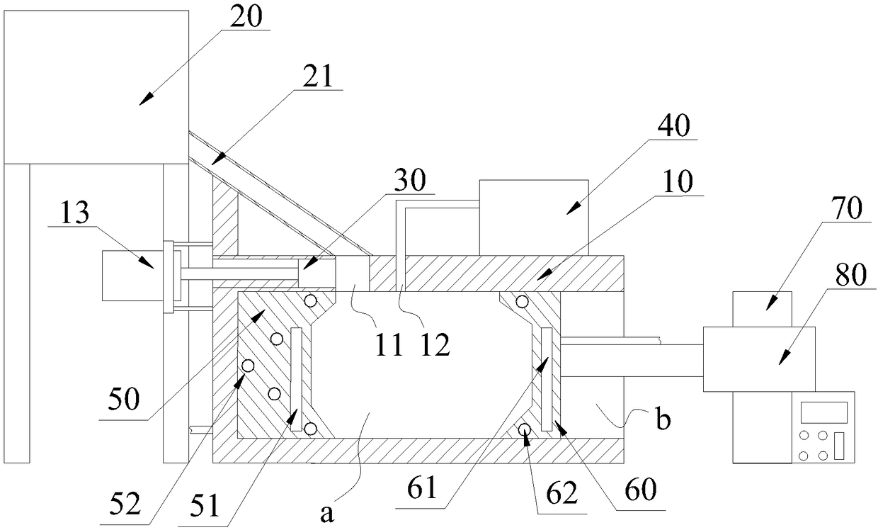
[0011] see figure 1 , figure 1 It is a structural schematic diagram of a die-casting machine for aluminum alloy parts of the present invention.
[0012] A die-casting machine for aluminum alloy parts, including a body 10, a molten aluminum furnace 20, an injection punch 30, and a vacuum pump 40, and also includes a fixed mold 50, a moving mold 60, a mounting column 70, and a first cylinder 80. Inside the body 10 There is a cavity a, one side of the cavity a is provided with an opening b, the opening b is arranged on the side of the body 10, the cavity a communicates with the outside atmosphere th...
PUM
Abstract
The invention relates to an aluminum alloy piece die-casting machine which comprises a body, a feeding pipe, an injection puncher pin, a vacuum pump, a fixed die, a movable die, an installing column and a first air cylinder, one end of the feeding pipe is connected with the body, a molten aluminum furnace is connected to the end, far away from the body, of the feeding pipe, the injection puncher pin is arranged in the body, the vacuum pump is connected with the body, the fixed die is arranged in the body, a first heating bar and a plurality of water pipes are arranged in the fixed die, the first heating bar is arranged inside the fixed die, the multiple first water pipes are evenly arranged inside the fixed die, the movable die is arranged at an opening, a second heating bar and a plurality of second water pipes are arranged in the movable die, the second heating bar is arranged inside the movable die, the multiple second water pipes are evenly arranged inside the movable die, the installing column is arranged on the side, away from the body, of the opening, the first air cylinder is fixedly installed on the installing column, the output end of the first air cylinder is fixedly connected with the movable die, and the movable die is in sliding connection to the interior of the body through the first air cylinder.
Description
technical field [0001] The invention relates to the technical field of metal processing equipment, in particular to a die-casting machine for aluminum alloy parts. Background technique [0002] Die casting is a metal casting process characterized by the application of high pressure to molten metal using the cavity of a mold. Molds are usually machined from stronger alloys, a process somewhat similar to injection molding. Most die castings are ferrous, such as zinc, copper, aluminum, magnesium, lead, tin, and lead-tin alloys and their alloys. Depending on the type of die casting, a cold chamber die casting machine or a hot chamber die casting machine is used. [0003] Because aluminum alloy has a good elongation rate and is lighter than other metals, it is favored by many industries, and aluminum alloy die-casting parts are also widely praised by the market. However, when the current die-casting equipment for aluminum alloy parts is cast at low mold temperature, When the a...
Claims
Application Information
Patent Timeline
Application Date:The date an application was filed.
Publication Date:The date a patent or application was officially published.
First Publication Date:The earliest publication date of a patent with the same application number.
Issue Date:Publication date of the patent grant document.
PCT Entry Date:The Entry date of PCT National Phase.
Estimated Expiry Date:The statutory expiry date of a patent right according to the Patent Law, and it is the longest term of protection that the patent right can achieve without the termination of the patent right due to other reasons(Term extension factor has been taken into account ).
Invalid Date:Actual expiry date is based on effective date or publication date of legal transaction data of invalid patent.