
Automatic PPR pipe fusion-welding robot and fusion-welding method

A robot and welding technology, which is applied in the field of automatic PPR pipe welding robot, can solve the problems of potential safety hazards, missing the best time and best state of pipe welding, and failure to reach it, so as to reduce waste, facilitate promotion and use, and greatly upgrade effect of space

Pending Publication Date: 2018-06-29
HARBIN UNIV OF SCI & TECH
View PDF3 Cites 3 Cited by
  • Summary
  • Abstract
  • Description
  • Claims
  • Application Information

AI Technical Summary

Problems solved by technology

[0003] The present invention aims to solve the problem that the manual welding of PPR pipes is limited by human operation, often fails to reach or miss the best time and best state of pipe welding, and easily leaves potential safety hazards, and further provides an automatic welding of PPR pipes. Welding robot and welding method using the robot

Method used


Image

  • Automatic PPR pipe fusion-welding robot and fusion-welding method
  • Automatic PPR pipe fusion-welding robot and fusion-welding method

Examples


specific Embodiment approach 1

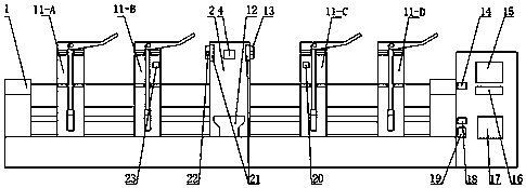
[0013] Specific implementation mode one: see figure 1 To illustrate this embodiment, the automatic PPR pipe welding robot and welding method include a base 1, a die clamping unit 2 is arranged in the middle above the base 1, and two sides of the die clamping unit 2 are provided with Die heads 13 of different types can be used. The die head 13 is provided with a temperature sensor 22. The back of the die head 13 on both sides is provided with a heating core 21. The heating core 21 is connected to the die head 13. An infrared thermal imaging camera 4 is arranged in the middle of the die clamping unit 2; pipe clamping units 3 are arranged on both sides of the die clamping unit 2, and four sets of clamps 11-A, 11-B, 11-C, 11-D, the fixtures 11-B, 11-C are respectively provided with a laser transmitter 20 and a laser receiver 23; the right side of the base 1 is provided with a single-chip motherboard 17, so The top of the single-chip microcomputer mainboard 17 is provided with a b...

specific Embodiment approach 2

[0014] Specific implementation method two: please refer to figure 1 Describe this embodiment, the automatic PPR pipe robot and welding method, the die head clamping unit 2 slides along the die head guide rail 12 .

specific Embodiment approach 3

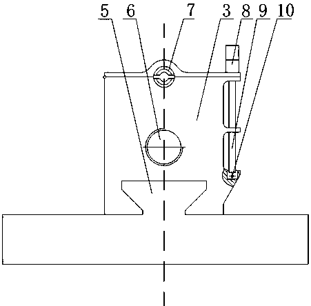
[0015] Specific implementation method three: please refer to figure 2 Describe the present embodiment, the automatic PPR pipe robot and welding method, the pipe clamping unit is provided with 6 lead screws, clamps 11 and clamp guide rails 5; the lead screw 6 and the stepper motor 14 are in phase connection; the clamp 11 is provided with positive and negative threads to spirally connect with the lead screw 6 and move along the clamp guide rail 5; the inside of the clamp is provided with a rubber washer 7, and the clamp 11 is provided with a wrench 8, so The wrench 8 adopts a cam structure to make the connection tighter; a screw 9 is arranged under the wrench 8, and the screw 9 and the clamp are connected by a pin 10 to fine-tune the tightness of the mechanism, so the pipe clamping unit 3 can be used To clamp pipes of different specifications, and under the control of the single-chip microcomputer 17, automatic docking can be realized.


PUM


Abstract

The invention relates to an automatic PPR pipe fusion-welding robot and a fusion-welding method, which belong to the field of pipe fusion-welding and intelligent control, and aim to solve the problemsthat the manual fusion-welding of a PPR pipe is affected by the manual operation strength, a pipe propelling angle, the environment temperature, the processing time and other factors. The automatic PPR pipe fusion-welding robot comprises a base, wherein a die head clamping unit capable of heating different types of die heads is arranged in the middle of the upper part of the base; pipe clamping units are arranged on two sides of the die head clamping unit; fixtures are arranged on the pipe clamping units and are used for clamping pipes with different specifications; a laser transmitter and alaser receiver are arranged on the fixtures; and a single chip microcomputer drives a screw rod to feed along a guide rail, so that the automatic fusion-welding operation with the best fusion-weldingtemperature, heating time, hot-melting depth and fusion-welding time is realized. According to the automatic PPR pipe fusion-welding robot and the fusion-welding method provided by the invention, theautomatic fusion-welding of pipes and pipe fittings with different specifications can be realized, and the fusion-welding is carried out at the best time, temperature and position, the reliability offusion-welding is ensured, and the fusion-welding efficiency is improved.

Description

technical field [0001] The invention relates to an automatic PPR pipe welding robot and a welding method of the welding robot, belonging to the field of pipeline welding and intelligent control. Background technique [0002] PPR pipes are widely used in building water supply and drainage, urban and rural water supply and drainage, industrial fluid transportation, agricultural irrigation, etc. , industry and agriculture. At present, PPR pipe hot-melt tools on the market are generally fully manual operations. The pipe is manually pushed into the heating die of the fusion splicer. With the experience of the operator, the pipe is removed from the die at the same time as soon as the processing time is reached, and then manually quickly and seamlessly. Evenly inserted to the desired depth while rotating, the welding is completed. This manual method is affected by factors such as human operating force, pipe propulsion angle, ambient temperature, processing time, etc., resulting i...

Claims


Application Information

Patent Timeline
Patent Type & Authority Applications(China)
IPC IPC(8): B29C65/02B29C65/18B29C65/78
CPCB29C65/02B29C65/18B29C65/7841B29C66/5221B29C66/863B29C66/91421
Inventor 徐守波徐雯雯罗淑琴房国志孙康瞳
Owner HARBIN UNIV OF SCI & TECH
Learn More