Travel control apparatus of brick laying machine

A technology for the stroke and control device of a brick laying machine, which is applied in the direction of roads, road repairs, roads, etc., can solve problems such as low work efficiency, increased construction budget, and waste of labor, and achieves the effects of convenient operation, simple structure, and accurate and consistent strokes

Pending Publication Date: 2018-06-29
夏江
View PDF14 Cites 0 Cited by
  • Summary
  • Abstract
  • Description
  • Claims
  • Application Information

AI Technical Summary

Problems solved by technology

[0002] With the improvement of my country's infrastructure construction, more and more brick roads are laid on sidewalks in the process of urban construction. Many brick roads are often laid one by one manually. In addition, the roads are getting wider and wider. The requirements for smoothness are also getting higher and higher. The pavement that needs to be paved is not only large in size, but also highly technically difficult. It also requires a lot of manual continuous work, which wastes a lot of labor. At the same time, the labor is often very expensive and the work efficiency is very low. , greatly increasing the construction budget
[0003] Since the existing brick laying machine adopts the continuous or slope brick laying method, the brick laying machine does not have the function of laying dust at the same time, or does not have the function of applying an adhesive layer to the back of the floor tiles, and cannot meet the high standard brick laying process. People have higher and higher requirements for tile laying, and the technology has more finer requirements th...

Method used


Image

  • Travel control apparatus of brick laying machine
  • Travel control apparatus of brick laying machine
  • Travel control apparatus of brick laying machine

Examples


Embodiment 1

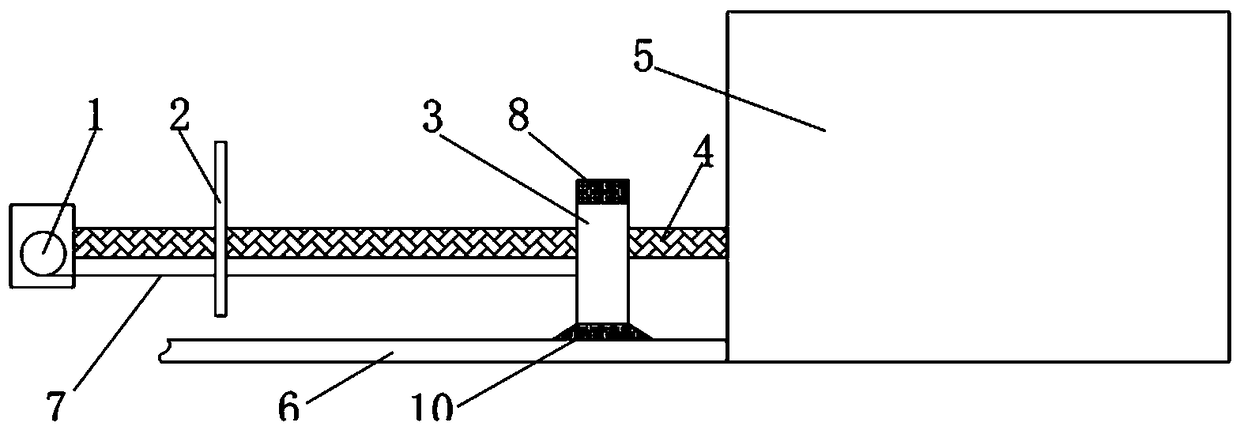
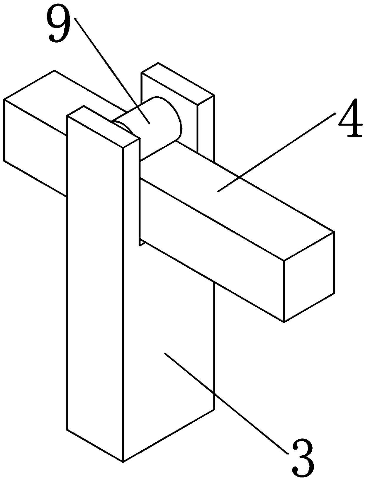
[0024] Such as figure 1 and figure 2 As shown, the stroke control device of the brick laying machine includes a coiler 1, a baffle plate 2, a parking device 3 and a guide rail 4. The guide rail 4 is located above the track 6 of the brick laying machine 5 and is parallel to each other. The guide rail 4 is installed on the brick laying machine 5 front end, the guide rail 4 extends along the front end of the brick laying machine 5 to the direction of movement, and the parking device 3, the baffle plate 2 and the coiler 1 are sequentially distributed outward, and the parking device 3 is provided with a limit switch, and the brick laying machine 5 The position corresponding to the parking device 3 on the baffle 2 is also equipped with a matching limit switch. The retractor 1 is composed of a retracting device with a built-in elastic sheet and a retractable pull rope 7, and the pull rope 7 passes through the baffle 2 Connect with parker.

[0025] The upper end of the parking devi...

Embodiment 2

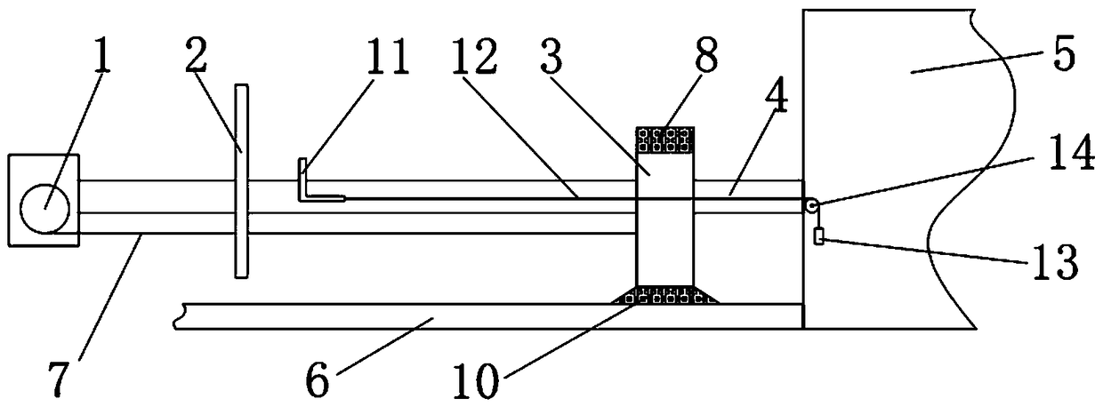
[0033] Such as image 3 and Figure 4As shown, the specific implementation is the same as in Example 1, the difference is that: an intercepting hook 11 is installed at one end of the baffle plate 2 on the guide rail 4, and the intercepting hook 11 moves back and forth near one end of the baffle plate on the guide rail, and the intercepting hook 11 is L-shaped. The lower end is connected to the guide rope 12 to make piston movement in the guide rail 4, and the upper end extends out of the guide rail 4. The other end of the guide rope is provided with an inertial body 13, and a guide wheel 14 is installed at the end of the guide rail 4, so that the guide rope can be pulled outside the guide rail after passing the guide wheel. The inertial body sags naturally. The inertial body 13 is made up of a central axis 15, a spring 16, and a falling body 17. The central axis 15 is a ⊥-shaped structure. A hole suitable for the size of the central axis is set at the center of the falling bod...

Embodiment 3

[0036] Such as Figure 5 As shown, the specific implementation is the same as in Example 1, and the difference is that the guide rail 4 is installed between the front and rear wheels of the brick laying machine 5, and the guide rail 4 is along the brick laying machine 5 (in the figure, only the frame of the brick laying machine 5 The rear wheel extends to the front wheel. On the guide rail 4, the parking device 3, the baffle 2 and the retractor 1 are distributed sequentially from the rear wheel to the front wheel. The purpose of stopper 3 swinging left and right. The coiler 1 is installed on the parking device 3, and the end of the stay rope passes through the baffle and is fixed on the brick laying machine in front of the baffle, so as to simplify the device and facilitate installation.

[0037] When this device is used in combination with a brick laying machine, guide rails are installed between the front and rear wheels of the brick laying machine and on the track, and lim...


PUM


Abstract

The invention relates to the technical field of brick laying machines, in particular to a travel control apparatus of a brick laying machine, which solves the problem about the travel positioning of an old brick laying machine. The travel control apparatus of the brick laying machine is characterized in that a guide rail is disposed above a brick laying machine track and is parallel to the brick laying machine track, a stopping device, a baffle plate and a winding device are successively distributed along the moving direction of the brick laying machine, the stopping device is provided with alimiting switch, the brick laying machine and the baffle plate are provided with a limiting switch matched therewith, and a pulling rope penetrates through the baffle plate to be connected with the stopping device; the upper end of the stopping device is provided with a concave sliding groove, the sliding groove is sleeved into the guide rail, the sliding groove is provided with a push-pull electromagnet, the bottom of the push-pull electromagnet is provided with a pulley in a hanging manner, a rotating shaft of the pulley is fixed on a push-pull rod of the push-pull electromagnet, and a pulley is disposed on the guide rail in the sliding groove; and the lower end of the stopping device is provided with an electromagnetic suction cup, and the electromagnetic suction cup is disposed on a track of the brick laying machine. By adopting the travel control apparatus, the working efficiency of the old brick laying machine can be effectively increased, on the premise of not performing the complicated and high-cost modification and upgrading of devices, the automatic reciprocating work of the brick laying machine is realized, and the modification cost is decreased.

Description

technical field [0001] The invention relates to the technical field of brick laying machines, in particular to a stroke control device for brick laying machines. Background technique [0002] With the improvement of my country's infrastructure construction, more and more brick roads are laid on sidewalks in the process of urban construction. Many brick roads are often laid one by one manually. In addition, the roads are getting wider and wider. The requirements for smoothness are also getting higher and higher. The pavement that needs to be paved is not only large in size, but also highly technically difficult. It also requires a lot of manual continuous work, which wastes a lot of labor. At the same time, the labor is often very expensive and the work efficiency is very low. , so that the construction budget is greatly improved. [0003] Since the existing brick laying machine adopts the continuous or slope brick laying method, the brick laying machine does not have the func...

Claims


Application Information

Patent Timeline
IPC IPC(8): E01C19/52
CPCE01C19/52
Inventor 夏舒琼
Owner 夏江
Why Eureka
Try Eureka