
Anti-freezing and braking system cooling device for automobile oil supply system

A technology of fuel supply system and braking system, which is applied in the direction of heat treatment device for fuel, arrangement combined with fuel supply of internal combustion engine, power device, etc., can solve problems such as uneconomical, loss of braking ability, and hidden safety hazards.

Inactive Publication Date: 2018-06-29
辛高腾
View PDF0 Cites 0 Cited by
  • Summary
  • Abstract
  • Description
  • Claims
  • Application Information

AI Technical Summary

Problems solved by technology

[0002] 1. For automobiles in the cold weather in the north in winter, when the fuel supply system is under the low temperature environment below -5°C, the technical indicators such as the kinematic viscosity and flash point of the diesel oil will be seriously reduced, resulting in no fuel, bad combustion, and harmful emissions. Even if the most expensive -35# diesel is used, its high energy consumption and high emissions are still unavoidable. A large amount of harmful emissions is one of the main causes of severe smog in northern China; therefore, diesel engines in winter in the north Anti-freezing and heating up the oil supply system is an important technical measure to reduce energy consumption and reduce harmful emissions; 2. In the braking system of a car, brake pads are the most critical safety parts, and all braking effects are determined by the brake pads Therefore, good brake pads are the patron saint of the driver and the car; brake pads are mainly divided into drum brakes and disc brakes. , When the car goes downhill for a long time, the temperature of the friction pads on the brake pads rises rapidly. Generally, the temperature of the brake pads for non-continuous braking is about 130°C, and the temperature for long-distance braking and continuous braking rises sharply, about 200-300°C. If it exceeds the test limit of 350°C, the braking ability may be lost, causing a great safety hazard; too high temperature is the main reason for the brake pads to decline, which directly affects the braking performance, so the cooling of the brake pads becomes particularly important; in addition : 1. In the past, the fuel supply system was heated by electric heating or automobile exhaust preheating and heating. First, it was uneconomical, and starting the car increased fuel consumption; second, it was inconvenient, and the effect could not be guaranteed after the car stopped; second, it was not To be safe, the circuit and oil circuit should be completely separated; 2. The cooling technology of the brake pads has always been the water tank spray cooling method. First, it wastes water resources; second, the water tank increases the load of the vehicle and increases fuel consumption; third. In summer, the water temperature of the water tank is high and the cooling effect is not obvious; Fourth, in winter, the cooling effect of spraying water on the road leads to the formation of ice bands on the road surface, which increases safety hazards; The cooling device of the brake system is of great significance

Method used


Image

  • Anti-freezing and braking system cooling device for automobile oil supply system

Examples


Embodiment 1

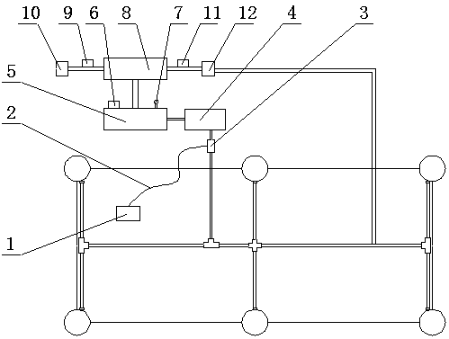
[0016] Such as figure 1 As shown, a device for antifreezing of automobile oil supply system and cooling of brake system, which includes a cold and hot gas generator 4, an air storage tank 5 and a control circuit 2, and the control circuit 2 is connected to the control switch 1 and the solenoid valve 3. The solenoid valve 3 is connected to a cold air generator 4, the cold air generator 4 is connected to an air storage tank 5, and the air storage tank 5 is connected to a cold and hot air generator 8, and the cold and hot air generator 8 A solenoid valve A9 is connected to the fuel tank heater 10 , and the hot and cold air generator 8 is connected to a solenoid valve B11 connected to a brake pad cooler 12 .

[0017] The purpose of this patent is to provide a diesel fuel system that uses hot air to prevent freezing of the fuel system such as the engine oil tank and uses cold air to cool down the brake pads of the car. The cooling device placed on the fuel tank is connected, and t...

Embodiment 2

[0019] Such as figure 1 As shown, a device for antifreezing of automobile oil supply system and cooling of brake system, which includes a cold and hot gas generator 4, an air storage tank 5 and a control circuit 2, and the control circuit 2 is connected to the control switch 1 and the solenoid valve 3. The solenoid valve 3 is connected to a cold air generator 4, the cold air generator 4 is connected to an air storage tank 5, and the air storage tank 5 is connected to a cold and hot air generator 8, and the cold and hot air generator 8 A solenoid valve A9 is connected, the solenoid valve A9 is connected with a fuel tank heater 10, the hot and cold air generator 8 is connected with a solenoid valve B11, and the solenoid valve B11 is connected with a brake pad refrigerator 12, and the hot and cold gas One end of the generator 8 is connected to a hot air pipe, and the other end is connected to a cold air pipe. The connection between the brake pad cooler 12 and the brake pad is a p...


PUM


Abstract

The invention relates to an anti-freezing and braking system cooling device for an automobile oil supply system. The device comprises a cold and hot gas generator, an air storage tank and a control circuit, the control circuit is connected with a control switch and an electromagnetic valve, and the electromagnetic valve is connected with a cold air generator; the cold air generator is connected with a gas storage tank, and the gas storage tank is connected with a cold and hot gas generator; the cold and hot gas generator is connected with an electromagnetic valve A, the electromagnetic valve Ais connected with an oil tank heater, and the cold and hot gas generator is connected with an electromagnetic valve B; the electromagnetic valve B is connected with a brake pad refrigerator; and therefore, the device has the advantages of being economical, practical, convenient to use and good in safety.

Description

technical field [0001] The invention belongs to the technical field of antifreezing and cooling of automobiles, and in particular relates to a device for antifreezing of an automobile fuel supply system and cooling of a brake system. Background technique [0002] 1. For automobiles in the cold weather in the north in winter, when the fuel supply system is under the low temperature environment below -5°C, the technical indicators such as the kinematic viscosity and flash point of the diesel oil will be seriously reduced, resulting in no fuel, bad combustion, and harmful emissions. Even if the most expensive -35# diesel is used, its high energy consumption and high emissions are still unavoidable. A large amount of harmful emissions is one of the main causes of severe smog in northern China; therefore, diesel engines in winter in the north Anti-freezing and heating up the oil supply system is an important technical measure to reduce energy consumption and reduce harmful emissi...

Claims


Application Information

Patent Timeline
IPC IPC(8): F02M31/16B60T5/00
CPCF02M31/16B60K2015/03427B60T5/00
Inventor 辛高腾
Owner 辛高腾
Learn More