
Rainwater and sewage gravity potential energy collecting device

A technology of gravitational potential energy and collection devices, applied in water supply devices, hydroelectric power generation, waterway systems, etc., can solve the problems of high speed of discarded rainwater and sewage, low power generation efficiency, and low use value, achieving significant energy saving and environmental protection benefits and high use value , large conversion effect

Inactive Publication Date: 2018-06-29
CENT SOUTH UNIV
View PDF8 Cites 2 Cited by
  • Summary
  • Abstract
  • Description
  • Claims
  • Application Information

AI Technical Summary

Problems solved by technology

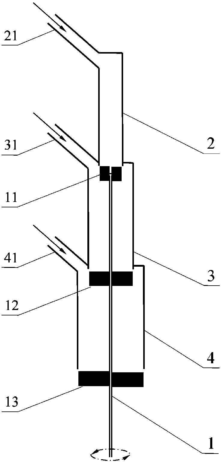
[0007] In order to overcome many problems such as short running time, high speed of discarded rainwater and sewage, small power generation, low use value and low power generation efficiency of single-stage water turbines, many equipments, complex systems and inconvenient installation of single-stage water turbines used in parallel, the present invention provides A "single water turbine, coaxial multi-stage impellers, small upper and lower large impellers" and other structural features, "multi-stage conversion of gravity potential energy, serial conversion of gravity potential energy, impact conversion of gravity potential energy, independent use of rainwater and sewage at each layer " and other technical characteristics, "less equipment, simple system, convenient installation, low flow rate of waste rainwater sewage, high potential energy conversion rate, large conversion amount, high use value" and other technical advantages of rainwater gravity potential energy collection device

Method used


Image

  • Rainwater and sewage gravity potential energy collecting device
  • Rainwater and sewage gravity potential energy collecting device

Examples


Embodiment Construction

[0013] The present invention will be further described below in conjunction with the accompanying drawings.

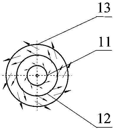
[0014] as attached figure 1 And attached figure 2 As shown, the rainwater and sewage gravitational potential energy collection device mainly includes a water turbine 1, a roof drain pipe 2, a second floor drain pipe 3 and a first floor drain pipe 4. The top of the first floor drainage pipe 4 is connected to the edge of the first floor sewage inlet and the outlet edge of the first floor sewage diversion pipe 41 without leakage, and the central axis of the diversion pipe 41 intersects with the central axis of the first floor drainage pipe 4 . The edge of the second-floor sewage inlet at the top of the second-floor drainage pipe 3 is connected to the outlet edge of the second-floor sewage diversion pipe 31 without leakage, and the central axis of the diversion pipe 31 intersects with the central axis of the second-floor drainage pipe 3 . The roof rainwater inlet edge a...


PUM


Abstract

The invention provides a rainwater and sewage gravity potential energy collecting device. The rainwater and sewage gravity potential energy collecting device comprises a water turbine, a roof drainagepipe, a second-floor drainage pipe and a first-floor drainage pipe, wherein the water turbine main shaft, the roof drainage pipe, the second-floor drainage pipe and the first-floor drainage pipe sequentially sleeve from inside to outside by taking the central axis of the water turbine main shaft as the center, a water turbine is sequentially provided with an upper impeller, a middle impeller anda lower impeller from top to bottom along the main shaft, and the distances of the positions of the highest points of the upper impeller, the middle impeller and the lower impeller lower than the bottom surfaces of an upper middle floor drain pipe and a lower middle floor drain pipe are 10-20 mm, the central axis of a sewage diversion pipe in one building is located on the same horizontal plane with the intersection point of the outer wall of the drainage pipe of the building and the highest point of the middle impeller, and the central axis of a second-floor sewage flow guide pipe is locatedon the same horizontal plane with the intersection point of the outer wall of the second-floor drainage pipe and the highest point of the upper impeller. Scattered distribution is collected in the rural and town energy-saving emission reduction resource recycling field, the gravity potential energy of the rain sewage and the small-power distributed energy station can be continuously discharged, and the device can be used. The rainwater and sewage gravity potential energy collecting device is little in investment, convenient to install, and compact in arrangement, and the converting efficiencyfrom the gravity potential energy to the rotating energy is 75%.

Description

technical field [0001] The invention belongs to the field of recycling and comprehensive utilization of energy-saving and emission-reducing resources in rural towns, and in particular relates to a rainwater and sewage gravity potential energy collection device suitable for efficiently converting rainwater and sewage gravity potential energy into rotational kinetic energy. Background technique [0002] National energy conservation and emission reduction, resource recycling and low-carbon life have become a subject of concern. [0003] A lot of rainwater sewage is usually collected and directly discharged into the sewage pipes. The sewage first flows into the vertical pipes, and then flows into the horizontal sewage pipes for discharge. When sewage falls from a high place, it contains abundant potential energy. Sewage enters from the upper end of the sewage pipe and accelerates down to the bottom. There is a lot of kinetic energy, but it is not further utilized in the current...

Claims


Application Information

Patent Timeline
IPC IPC(8): F03B3/12F03B11/00F03B13/00E03F3/04
CPCE03F3/04F03B3/12F03B11/00F03B13/00Y02E10/20
Inventor 艾元方胡鑫
Owner CENT SOUTH UNIV
Learn More